A water tank without reliable level monitoring is a liability. Overfills waste water and damage equipment. Run-dry events burn out pumps. Manual checks with dipsticks or sight glasses are unreliable and labor-intensive. We’ve seen all of these problems firsthand across water treatment plants, chemical storage facilities, and municipal reservoir systems.
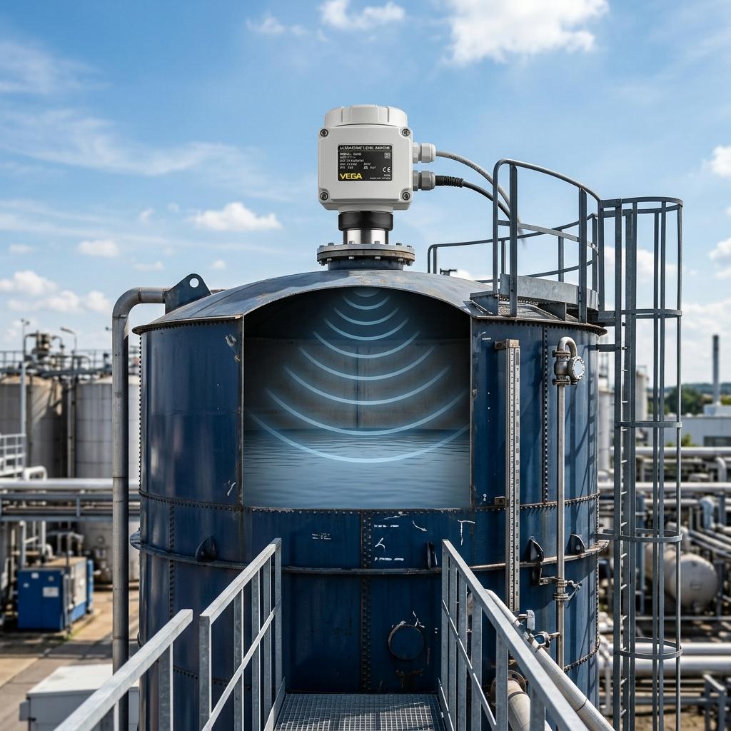
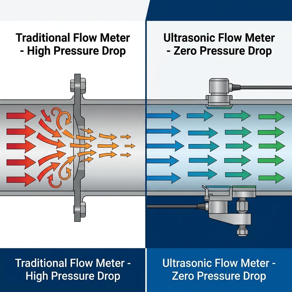
Ultrasonic level sensors solve this by measuring the distance from the sensor to the water surface using sound waves — no moving parts, no contact with the liquid, no maintenance headaches. Unlike flow measurement instruments that require pipe integration, level sensors mount externally above the tank and deliver real-time level data without any process interruption. But choosing the right ultrasonic sensor for your specific tank application isn’t as simple as picking one off the shelf. Tank size, chemical compatibility, environmental conditions, and output requirements all affect which model works best.
Quick Answer: Ultrasonic water level sensors use the time-of-flight principle to measure tank levels without contacting the liquid. For most water tank applications, choose a sensor with a measuring range that exceeds your tank height by at least 20%, account for the blind zone (typically 0.3–0.6 m) when planning mounting height, and select probe materials (ABS vs. PVDF/PTFE) based on whether corrosive vapors are present.
For a deeper look at how ultrasonic level sensing technology works, see our detailed working principle guide.
Why Ultrasonic Sensors Are the First Choice for Water Tank Level Monitoring
Not every level measurement technology suits water tanks. Here’s why ultrasonic consistently wins over alternatives for this specific application:
Non-Contact = Zero Contamination Risk
The sensor mounts above the liquid surface and never touches the water. This is critical for:
– Potable water tanks — no wetted materials to certify or replace
– Chemical dosing tanks — no corrosion of sensor elements
– Wastewater equalization basins — no fouling from suspended solids
No Moving Parts = Virtually Maintenance-Free
Unlike float switches that stick, pressure transmitters that clog, or radar transmitters that accumulate condensation on their antennas, ultrasonic sensors have a solid-state transducer with no mechanical wear components. In our experience, a properly installed ultrasonic level sensor runs for 3-5 years between service visits — typically just a quick cleaning of the transducer face.
Cost-Effective for the Accuracy Delivered
| Technology | Typical Accuracy | Relative Cost | Contact? | Maintenance |
|---|---|---|---|---|
| Ultrasonic | ±0.02–0.5% F.S. | Medium | No | Very Low |
| Float switch | Point level only | Low | Yes | Medium (mechanical wear) |
| Submersible pressure | ±0.25–0.5% F.S. | Medium | Yes | High (diaphragm fouling) |
| Radar | ±1–3 mm | High | No | Low |
| Capacitance | ±1–2% F.S. | Medium | Yes | Medium (coating buildup) |
For water tanks under 15 meters depth, ultrasonic sensors deliver the best balance of accuracy, cost, and reliability. Radar becomes the better choice only when you need millimeter-level precision or when the environment has heavy vapor/foam that disrupts ultrasonic signals.
How Ultrasonic Water Level Sensors Work
The operating principle is straightforward — time of flight (ToF):
- The transducer emits a burst of ultrasonic pulses (typically 20–200 kHz) downward toward the water surface
- The pulses travel through air, reflect off the water surface, and return to the transducer
- The sensor measures the round-trip time (T) and calculates distance:
Distance = (Speed of Sound × T) / 2
- The controller subtracts this distance from the programmed tank height to determine the actual water level
Temperature Compensation Matters
The speed of sound in air varies with temperature — approximately 331.3 m/s at 0°C and 346.1 m/s at 25°C. A 10°C temperature error translates to roughly 1.7% distance error. Our SR600/601/602 series sensors have built-in temperature compensation that continuously adjusts the speed-of-sound calculation, keeping accuracy within specification across the full -40°C to +70°C processing temperature range.
Understanding the Blind Zone
Every ultrasonic level sensor has a blind zone (also called dead zone or dead band) — a minimum distance from the transducer face where echoes cannot be reliably detected. This is because the transducer needs time to switch from “transmit” mode to “receive” mode.
| Model Series | Blind Zone | What This Means in Practice |
|---|---|---|
| SR600/601/602 (Integrated) | 0.45–0.6 m | Maximum water level must be at least 0.6 m below the sensor |
| Split Type | 0.3–0.6 m | Slightly better for tanks with limited headroom |
Critical installation rule: If your tank is 5 meters tall and the sensor has a 0.6 m blind zone, the maximum measurable water level is 4.4 meters. You must account for this when programming the sensor’s range and when designing alarm setpoints.
Choosing the Right Sensor: Selection Guide by Application
SR600/601/602 Series Overview
Our integrated ultrasonic level meter series covers most water tank applications. Here’s how to choose between models:
| Parameter | SR600-14/15 | SR601-13 | SR600-12 | SR602-10 | SR602-11 |
|---|---|---|---|---|---|
| Channel | Single | Single | Single | Double | Double |
| Housing | Aluminum (14) / Plastic (15) | ABS | PVDF/PTFE | ABS | PVDF/PTFE |
| Explosion-Proof | No | ExdIICT4Gb | ExdIICT4Gb | ExdIICT4Gb | ExdIICT4Gb |
| Corrosion-Resistant Probe | No (ABS) | No (ABS) | Yes (PVDF/PTFE) | No (ABS) | Yes (PVDF/PTFE) |
| Accuracy | ±0.025–0.5% | ±0.025–0.5% | ±0.025–0.5% | ±0.02% F.S. | ±0.02% F.S. |
| Measuring Range | 0–5m / 0–10m / 0–15m | 0–5m / 0–10m / 0–15m | 0–5m / 0–10m / 0–15m | 0–5m / 0–10m / 0–15m | 0–5m / 0–10m / 0–15m |
| Best For | General water tanks, HVAC | Flammable/explosive environments | Corrosive chemicals + Ex zones | High-accuracy dual-tank monitoring | Corrosive + explosive + high accuracy |
When to Use the Split (Divided) Type
The split-type ultrasonic level meter separates the transducer from the display/controller unit, connected by up to 50 meters of cable. Choose split over integrated when:
- High vibration environment — keep the sensitive electronics away from the tank
- Difficult viewing access — mount the display at operator eye level while the transducer sits on top of a tall tank
- Complex pump control — the split type includes 3 relay outputs for start/stop logic and high/low alarms, making it a standalone pump controller
- DCS integration — both 4-20mA and RS485 Modbus outputs for direct PLC/DCS connection
Split type specifications:
– Measuring range: 0–10 m
– Blind zone: 0.3–0.6 m
– Accuracy: 0.3%
– Cable length: up to 50 m between transducer and controller
Selection Decision Matrix
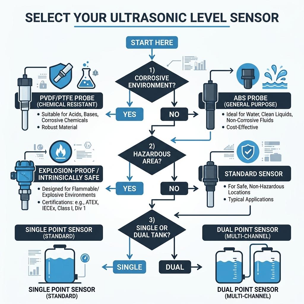
Use this flowchart to select the right model:
| Your Situation | Recommended Model | Why |
|---|---|---|
| Clean water tank, no hazardous area, budget-conscious | SR600-14 (Aluminum) or SR600-15 (Plastic) | Standard protection, lowest cost |
| Clean water tank in Zone 1/2 hazardous area | SR601-13 | ExdIICT4Gb certified, ABS probe |
| Chemical tank with corrosive vapors | SR600-12 | PVDF/PTFE probe resists acid/alkali |
| Chemical tank + hazardous area | SR602-11 | Corrosion-resistant + explosion-proof |
| Two tanks, high accuracy required | SR602-10 or SR602-11 | Dual-channel, ±0.02% F.S. |
| Tall tank (>10m) or need pump control | Split Type | Remote display + 3 relay outputs |
| HVAC chilled water buffer tank | SR600-14 | Compact, cost-effective, 4-20mA output |
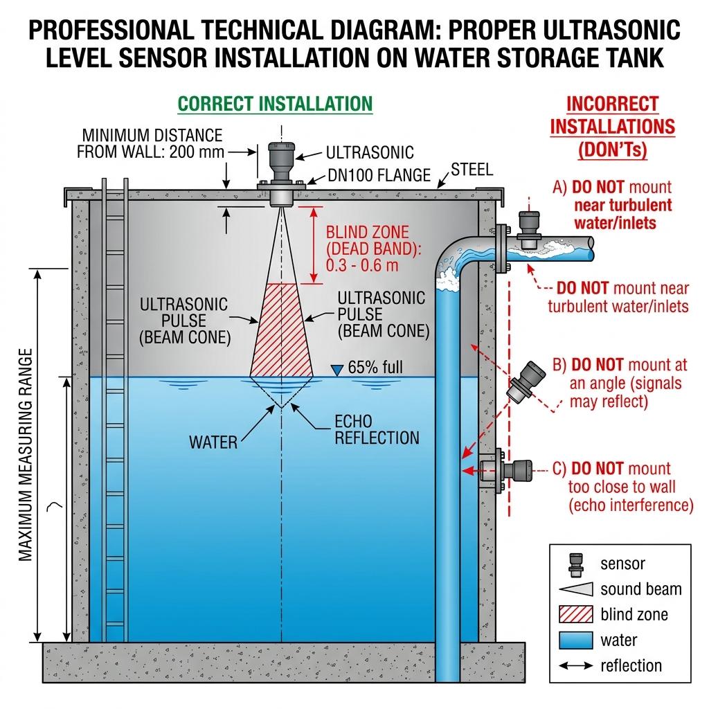
Installation Guide: Getting It Right the First Time
Proper installation is the single most important factor for reliable ultrasonic level measurement. Based on our field experience, over 70% of accuracy complaints we investigate trace back to installation issues, not sensor failures.
Mounting Position
DO:
– Mount the sensor perpendicular to the water surface (vertical, facing straight down)
– Position the sensor at least 200 mm away from the tank wall to avoid sidewall echo interference
– Install on a stable, vibration-free mounting point (bracket or flange)
– Ensure the beam path is clear of obstructions (pipes, ladders, agitators, baffles)
DON’T:
– Mount directly above the inlet pipe — turbulence and splashing create false echoes
– Mount near a corner — multiple reflections from adjacent walls cause signal confusion
– Mount at an angle — the beam reflects away from the transducer instead of back to it
– Mount where heavy condensation drips onto the transducer face
Beam Angle and Tank Geometry
The ultrasonic beam spreads at an angle as it travels downward (typically 5–12° cone angle). This means the “footprint” on the water surface grows larger with distance:
| Distance to Surface | Approximate Beam Diameter (8° cone) |
|---|---|
| 2 m | ~0.28 m |
| 5 m | ~0.70 m |
| 10 m | ~1.40 m |
| 15 m | ~2.10 m |
Why this matters: In narrow tanks (diameter < 1 m), the beam may hit the sidewall before reaching the water surface at longer distances. For narrow tanks, use a sensor with a smaller beam angle, or choose a guided-wave radar instead.
Blind Zone Planning
This is where we see the most mistakes. Here’s how to calculate your mounting height:
Mounting Height = Maximum Water Level + Blind Zone + Safety Margin
Example: Tank is 8 m tall, maximum water level is 7.5 m, sensor blind zone is 0.6 m:
– Mounting height above tank bottom = 7.5 + 0.6 + 0.1 (safety) = 8.2 m
– If your tank is only 8 m tall, you need a 200 mm standoff or nozzle on top
Process Connection Options
| Connection Type | When to Use |
|---|---|
| M59×2 Thread | Standard for most applications; screws into a threaded fitting on the tank roof |
| Bracket Mount | Open-top tanks or concrete reservoirs; adjustable angle |
| DN80 Flange | Pressurized tanks or where a sealed connection is required |
| DN100 Flange | Large nozzle openings; better for high-power transducers |
| Custom | Non-standard tank configurations |
Wiring and Power
- Two-wire 24V DC: Simplest installation — power and 4-20mA signal on the same two wires. Maximum cable run depends on load resistance (750Ω max).
- Four-wire 24V DC or 220V AC: Separate power and signal wires. Required when using relay outputs or RS485 communication.
- Cable entry: M20×1.5 or 1/2″ NPT — use waterproof cable glands rated to at least IP65.
Field Tip: In outdoor installations, always run the cable through conduit and add a drip loop before the cable entry point. We’ve seen water track along cables and into the electronics housing — a drip loop costs nothing and prevents a costly failure.
Ultrasonic vs. Submersible vs. Radar: Choosing the Right Technology
Different tank scenarios call for different technologies. Here’s an honest comparison based on our field experience deploying all three:
| Factor | Ultrasonic | Submersible Pressure | Radar |
|---|---|---|---|
| Contact with liquid | No | Yes (fully immersed) | No |
| Typical accuracy | ±0.02–0.5% F.S. | ±0.25–0.5% F.S. | ±1–3 mm |
| Measuring range | Up to 15 m | Up to 200 m+ | Up to 70–120 m |
| Affected by vapor/foam | Yes — major limitation | No | Minimal (FMCW radar) |
| Affected by temperature | Yes (compensated) | Minimal | No |
| Maintenance | Very low (clean face) | High (diaphragm clogging, cable replacement) | Low |
| Cost | Medium | Low–Medium | High |
| Best for | Clean water tanks <15 m | Deep wells, open channels, slurry tanks | Harsh environments, high accuracy, long range |
When Ultrasonic Is NOT the Right Choice
Be honest about the limitations — ultrasonic isn’t always the answer:
- Heavy foam on surface — foam absorbs ultrasonic energy; the echo never returns. Use radar or submersible instead.
- Thick vapor blanket — concentrated chemical vapors change the speed of sound unpredictably. Even temperature compensation can’t fix this.
- Tank height >15 m — signal attenuation becomes excessive. Switch to radar (up to 120 m with 80 GHz) or submersible level transmitter.
- Vacuum or pressurized vessels — ultrasonic needs air (or gas) as the transmission medium. Under vacuum, there’s insufficient medium for sound propagation. Under pressure, the speed of sound changes significantly.
- Extreme turbulence at the surface — splashing from high-velocity inlets scatters the beam. Solve this with a stilling well, or relocate the sensor.
For radar alternatives, see our radar level sensor comparison guide.
Troubleshooting: Common Problems and Solutions
Based on the issues we encounter most frequently during field service calls:
Signal-Related Issues
| Problem | Likely Cause | Solution |
|---|---|---|
| No reading / “Loss of Echo” | Sensor too far from surface; surface foam; transducer face dirty | Verify range setting; check for foam; clean transducer |
| Reading stuck at one value | False echo from obstruction in beam path | Identify and remove obstruction, or use “false echo suppression” feature |
| Erratic / jumping readings | Turbulent water surface; electrical interference | Install stilling well; add shielded cable; check grounding |
| Reading slowly drifts | Temperature compensation failure; condensation on transducer | Verify temp sensor function; clean and dry transducer face |
Level Accuracy Issues
| Problem | Likely Cause | Solution |
|---|---|---|
| Consistently reads too high | Programmed tank height incorrect; mounting height error | Re-measure and re-enter actual installation dimensions |
| Consistently reads too low | Speed of sound affected by non-air gas mixture | If non-air environment, apply manual speed-of-sound correction |
| Accuracy changes with temperature | Temperature compensation not activated or sensor defective | Verify temp comp is enabled; check built-in RTD sensor |
| 4-20mA output doesn’t match display | Output range not scaled correctly | Re-configure 4-20mA mapping (4mA = empty, 20mA = full) |
Environmental Issues
| Problem | Likely Cause | Solution |
|---|---|---|
| Condensation drops cause false echoes | Outdoor installation without protection | Add rain/sun shield; apply hydrophobic coating to transducer face |
| Readings affected by wind | Open-top tank with strong crosswinds | Install windscreen around sensor; increase signal averaging |
| Spiders/insects nest in transducer | Outdoor installation, warm climate | Install insect screen over transducer face |
Field Story: One of our most memorable troubleshooting calls was at a wastewater plant where the ultrasonic level sensor was giving random spikes every morning around 6 AM. After hours of checking wiring and settings, we discovered that a flock of pigeons was roosting on the tank roof — and their morning takeoff created enough surface disturbance to scatter the ultrasonic beam. The solution? A simple bird deterrent strip near the sensor. Sometimes the problem isn’t in the instrument.
Applications: Where Ultrasonic Water Level Sensors Excel
Water & Wastewater Treatment
- Raw water intake monitoring
- Clarifier and sedimentation tank levels
- Chemical dosing tank levels (use PVDF/PTFE probe)
- Filter backwash tank monitoring
- Treated water reservoir level control
Industrial Water Systems
- Cooling tower basin level (real-time monitoring for flow measurement optimization)
- Boiler feedwater tank monitoring
- Process water buffer tanks
- Fire water reserve tank monitoring (with alarm relay outputs)
Municipal & Agriculture
- Elevated water tower level monitoring
- Irrigation reservoir management
- Stormwater detention basin monitoring
- Groundwater recharge basin levels
HVAC & Building Management
- Chilled water buffer tank levels
- Hot water storage tank monitoring
- Condensate collection tank level control
For a comprehensive overview of ultrasonic level measurement applications across industries, see our application guide.
Technical Specifications: SR600/601/602 Series
| Parameter | Specification |
|---|---|
| Measuring Range | 0–5 m / 0–10 m / 0–15 m |
| Blind Zone | 0.45–0.6 m |
| Accuracy | ±0.02% F.S. (SR602) / ±0.025–0.5% (SR600/601) |
| Resolution | 1 mm |
| Processing Temperature | -40°C to +70°C |
| Processing Pressure | -0.02 to 0.1 MPa |
| Ambient Temperature | -20°C to +60°C |
| Signal Output | 4-20mA (optional HART protocol) |
| Power Supply | Two-wire 24V DC / Four-wire 24V DC / 220V AC |
| Protection Class | IP65 (ABS housing) / IP67 (Aluminum housing) |
| Process Connection | M59×2 Thread / Bracket / DN80 Flange / DN100 Flange / Custom |
| Display | Single-channel or Double-channel LCD |
| Cable Entry | M20×1.5 or 1/2″ NPT |
| Explosion-Proof | ExdIICT4Gb (SR601/602 models) |
| Probe Materials | ABS (standard) / PVDF or PTFE (corrosion-resistant) |
All specifications sourced from our product datasheet. For detailed dimensional drawings and ordering codes, contact our engineering team.
FAQ: Ultrasonic Water Level Sensors
What is the maximum range of an ultrasonic level sensor for water tanks?
Our SR600/601/602 series supports measuring ranges of 0–5 m, 0–10 m, and 0–15 m. For tanks taller than 15 meters, ultrasonic signal attenuation becomes a limiting factor — in these cases, we recommend switching to a radar level meter (up to 70–120 m range) or a submersible level transmitter. Most water storage tanks fall within the 0–15 m range, making ultrasonic the ideal choice.
Can ultrasonic level sensors work with corrosive liquids?
Yes, but with the right probe material. Standard ABS probes are suitable for clean water, wastewater, and non-aggressive chemicals. For tanks containing acids, alkalis, or solvents that produce corrosive vapors, choose a model with a PVDF or PTFE probe (our SR600-12 or SR602-11). Remember — the sensor doesn’t touch the liquid, but the probe face is exposed to vapors above the surface, which is where corrosion occurs.
How does foam affect ultrasonic level measurement?
Foam is the biggest enemy of ultrasonic level sensors. Light foam (thin layer, large bubbles) typically causes minor signal attenuation — readings may become noisier but still usable. Heavy foam (thick, dense, small bubbles) can absorb the ultrasonic pulse completely, causing “loss of echo” errors. If your application has persistent heavy foam, consider a radar level sensor instead — radar signals penetrate foam much more effectively than ultrasound.
What is the blind zone and why does it matter?
The blind zone is the minimum distance from the transducer face where reliable measurement is not possible (0.3–0.6 m for our sensors). If the water level rises into the blind zone, the sensor cannot detect it and may display incorrect readings or errors. When installing, ensure the maximum possible water level stays below the blind zone boundary. This is especially important for small tanks or tanks that routinely fill to near-capacity.
Do I need explosion-proof certification for a water tank sensor?
For standard clean water storage tanks — no. But explosion-proof certification (ExdIICT4Gb) is required when:
– The tank contains flammable liquids or produces flammable vapors
– The sensor is installed in a classified hazardous area (Zone 1 or Zone 2)
– Local safety regulations mandate it (common in petrochemical and wastewater facilities near methane-producing processes)
Our SR601 and SR602 series carry ExdIICT4Gb certification. If you’re unsure about your zone classification, consult your plant safety engineer before ordering.
How often should I clean or maintain an ultrasonic level sensor?
Under normal conditions, ultrasonic sensors require very little maintenance. We recommend:
– Every 6 months: Visual inspection of the transducer face for dust, spider webs, or condensation buildup
– Every 12 months: Verify readings against a manual measurement (tape measure or dipstick)
– As needed: Clean the transducer face with a soft cloth and mild soap if signal strength degrades
In dusty or high-humidity environments, increase inspection frequency to quarterly. The sensors themselves have no consumable parts — there’s nothing to replace under normal operation.
Can I use an ultrasonic level sensor in an open-top tank?
Yes, but with precautions. Open-top tanks expose the sensor to wind, rain, and temperature fluctuations. Install a rain/sun shield over the sensor, and increase the signal averaging setting in the controller to smooth out surface disturbances caused by wind. For large open basins, consider mounting the sensor inside a stilling well — a vertical tube that extends from above the sensor down into the water. The stilling well calms the surface within the measurement zone while still allowing water level changes to register.
Conclusion
Choosing the right ultrasonic water level sensor for your tank application comes down to five key decisions:
- Measuring range — Match sensor range to tank height plus 20% margin
- Blind zone — Plan mounting height to keep maximum water level below the blind zone
- Probe material — ABS for clean water, PVDF/PTFE for corrosive vapors
- Explosion-proof rating — Required for hazardous area classifications
- Output type — Simple 4-20mA for analog systems; RS485 Modbus or HART for digital integration
For tanks under 15 meters with clean to mildly aggressive liquids, our SR600/601/602 series provides the reliability, accuracy, and low maintenance that water treatment professionals need.
Need Help Selecting the Right Ultrasonic Level Sensor?
Our engineering team at Soaring Instrument specializes in level measurement solutions for water treatment, chemical processing, and industrial tank monitoring. Whether you need help selecting between integrated and split-type sensors, need guidance on hazardous area certification, or want a customized solution for an unusual tank geometry, we’re here to help.
👉 Contact our team for a free consultation
📧 Or email us directly at [email protected]
Related Articles
- Can Ultrasonic Level Sensors Effectively Monitor Water Tank Levels?
- How Does an Ultrasonic Level Sensor Work in Industrial Applications?
- How Do Ultrasonic Level Sensors Work for Tank Monitoring?
- What Are the Key Applications of Ultrasonic Level Measurement?
- What’s the Best Way to Measure Diesel Tank Levels with Ultrasonic Sensors?
- What’s The Real Difference Between Radar and Ultrasonic Level Sensors?
- Submersible Level Transmitter Maintenance Guide for Wastewater Applications
- How to Choose and Use Level Switches for Tank Applications?
- How To Accurately Measure Tank Level With Differential Pressure Transmitters?