Quick Answer: Submersible level transmitter maintenance in wastewater applications requires cleaning the sensor head every 1–3 months, annual recalibration, quarterly cable integrity checks, and surge protection. Neglecting these steps causes inaccurate readings, signal drift, and premature failure—costing far more than preventive care.
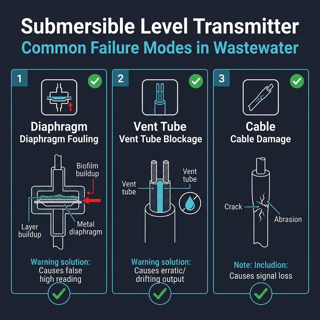
Wastewater is one of the harshest environments any instrument can face. We’ve seen it firsthand: a submersible level transmitter installed in a municipal lift station working perfectly for the first year—then silently drifting 8% off-reading by month 18 due to biofilm buildup on the diaphragm. The pump control system kept running based on false liquid level data, eventually causing an overflow event that required a full-tank shutdown.
That failure was completely preventable. This guide gives wastewater engineers and instrumentation technicians the exact maintenance framework we use at Soaring Instrument to keep submersible level transmitters accurate, reliable, and long-lived in demanding wastewater environments.
For context on our level measurement product line, see: Ultrasonic vs Radar Level Transmitter: Which Should You Choose?
What Is a Submersible Level Transmitter?
A submersible level transmitter (also called a hydrostatic level transmitter or submersible pressure transducer) is a contact-type liquid level measurement device designed to be fully submerged in liquid. It measures the hydrostatic pressure exerted by the liquid column above the sensor, then converts that pressure into an electrical signal—typically 4–20 mA—proportional to the liquid level.
The core components are:
– Piezoresistive sensing element – converts pressure to voltage
– 316 stainless steel housing – corrosion-resistant enclosure
– Signal/vent cable – transmits output and compensates for atmospheric pressure
– Protective nose cone or guard – shields the diaphragm from physical impact
Why wastewater is uniquely challenging:
| Challenge | Impact on Transmitter |
|---|---|
| Sludge & biofilm buildup | Clogs diaphragm → inaccurate readings |
| H₂S gas | Corrodes stainless steel and cable jacket |
| Suspended solids | Abrades sensing membrane over time |
| Lightning at outdoor lift stations | Destroys electronics without surge protection |
| Frequent level fluctuations | Accelerates cable fatigue at entry points |
Our Soaring Submersible Level Transmitter is specifically designed for these conditions—featuring stable performance, high sensitivity, multiple customizable pressure ranges, reverse polarity and over-voltage protection, and corrosion-resistant construction suitable for multi-range media including wastewater and slurry.
How a Submersible Level Transmitter Works in Wastewater
Understanding the working principle helps you identify why specific maintenance steps matter.
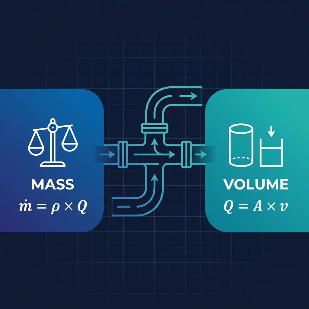
Hydrostatic pressure measurement formula:
P = ρ × g × h
Where:
– P = hydrostatic pressure (Pa)
– ρ = fluid density (kg/m³)
– g = gravitational acceleration (9.81 m/s²)
– h = liquid level height above sensor (m)
The transmitter continuously measures P and back-calculates h. This means any factor that changes the pressure at the sensing element—fouling, bubble entrainment, or cable vent blockage—produces inaccurate readings.
The vent tube in the cable equalizes the reference side of the differential pressure sensor to atmospheric pressure. If this vent tube becomes blocked with moisture or particulate, the transmitter will output an incorrect reading even though the sensing element itself is undamaged.
The 5-Point Wastewater Maintenance Framework
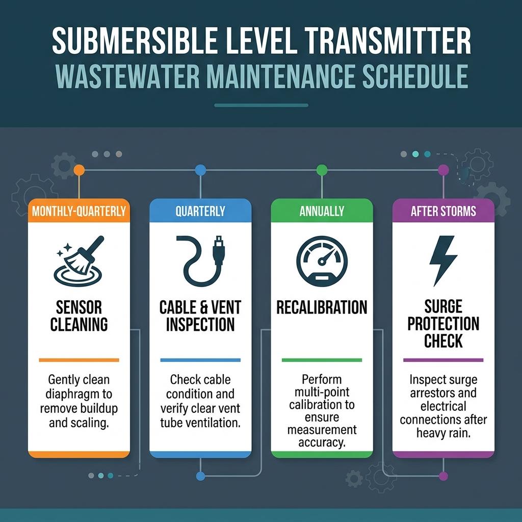
Based on our field experience across municipal wastewater plants, lift stations, and industrial effluent systems, we recommend this structured maintenance schedule:
1. Sensor Head Cleaning (Every 1–3 Months)
Why it matters: Sludge, algae, grease, and calcium carbonate deposits accumulate on the stainless steel diaphragm. Even a thin biofilm layer—1–2 mm—can create enough pressure differential to shift readings by 3–5% of full scale.
Procedure:
- Safely retrieve the transmitter using the suspension cable (never the signal cable)
- Rinse with clean water to remove loose debris
- Use a soft bristle brush or lint-free cloth—never metal tools or abrasive pads
- For scale deposits: apply diluted acetic acid (white vinegar, 5–10%) for 5–10 minutes, then rinse thoroughly
- Inspect the diaphragm face visually for pitting, deformation, or cracks
- Re-submerge carefully, avoiding impact with tank walls or bottom
⚠️ Critical rule: Never use hydrochloric acid or alkaline cleaners on 316 SS diaphragms. Chloride attack causes pitting corrosion that permanently damages the sensing surface—the exact failure mode we see most often in poorly maintained wastewater installations.
Frequency guidance by application:
| Application | Recommended Interval |
|---|---|
| Clean influent/effluent | Every 3 months |
| Activated sludge basin | Every 1–2 months |
| Lift station wet well | Every 1–2 months |
| Primary clarifier | Every 2–3 months |
| Digester/sludge tank | Every 1 month |
2. Cable Integrity and Vent Tube Inspection (Every 3 Months)
Why it matters: The cable serves dual functions in most submersible level transmitters: it carries the 4–20 mA signal and contains the atmospheric reference vent tube. Damage to either function causes measurement error.
What to inspect:
- Physical damage: Look for cuts, kinks, abrasions, or compression marks along the full cable length. Pay particular attention to the cable entry point at the transmitter body and at cable clamps or conduit entries—these are highest-stress locations.
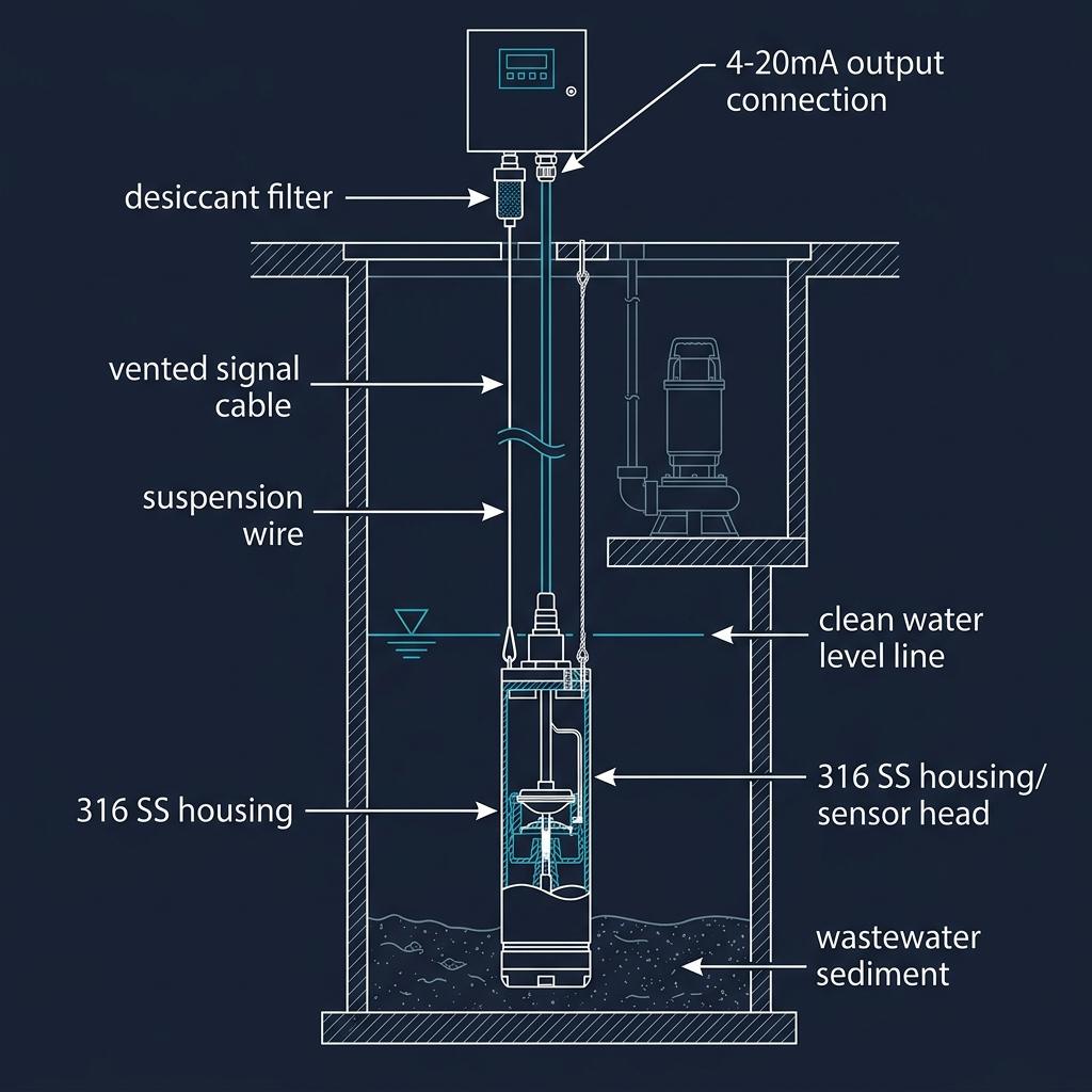
- Vent tube integrity: Ensure the vent opening (usually at the control panel end of the cable) is clear and protected by a desiccant filter or breather cap.
- Cable jacket condition: Polyurethane jackets yellow and crack over time when exposed to H₂S and UV. ETFE jackets offer better chemical resistance for aggressive wastewater.
- Tensile strength: The suspension cable or a separate stainless steel support wire must bear the transmitter weight—never the signal cable alone.
Desiccant filter maintenance:
The desiccant cartridge at the cable end absorbs moisture that would otherwise travel down the vent tube and block atmospheric pressure compensation. Replace the desiccant cartridge annually, or when the silica gel indicator turns pink.
Lessons from the Field:
In one lift station project, a submersible level transmitter had been delivering increasingly erratic readings over six months. The instrumentation technician initially suspected a failing sensing element. Upon inspection, we found the vent tube at the cable top had been pushed into the conduit during installation, completely blocking airflow. The “faulty sensor” was actually working perfectly—it just couldn’t compensate for atmospheric pressure changes. Clearing the vent tube and repositioning the cable entry restored accurate measurement immediately. The repair took 20 minutes. The diagnostic process had taken six weeks.
3. Recalibration and Verification (Annually, or After Any Major Event)
Why it matters: Piezoresistive sensing elements experience long-term zero drift and span shift due to temperature cycling, pressure overloads, and diaphragm fatigue. Annual recalibration ensures your level measurements remain within specification.
Verification procedure (field method):
- Note the transmitter output reading (mA or engineering units)
- Measure actual liquid level using a calibrated dipstick, sight glass, or portable ultrasonic sensor
- Compare readings: deviation > ±1% of span requires recalibration
- If deviation is within tolerance: document and continue
- If deviation exceeds tolerance: follow manufacturer’s zero/span adjustment procedure or return for factory calibration
Calibration triggers (beyond annual schedule):
- Transmitter was exposed to pressure overload (pump surge, water hammer)
- Pressure ranges changed (e.g., tank retrofitted to increase depth)
- Cable was replaced
- Transmitter was moved to a different installation point
- Process temperature range changed significantly
- Reading discrepancy reported by SCADA operators
For more on calibration standards in flow and level instrumentation, see: What Do You Need to Know About Flow Meter Calibration?
4. Surge and Lightning Protection (Inspect After Storm Events)
Why it matters: Outdoor wastewater installations—lift stations, wet wells, open aeration basins—are highly exposed to lightning ground strike transients. A single lightning event can destroy the transmitter electronics instantly.
Protection measures:
- Install loop-powered surge arrestors on the 4–20 mA signal line at the field junction box
- Ensure proper earth grounding of the transmitter housing and cable shield
- After any significant lightning event, verify transmitter output at 0% and 100% level reference points
- Inspect cable for burn marks or jacket damage at connection points
Our Soaring Submersible Level Transmitter includes built-in shock and lightning resistance as a standard feature—this significantly reduces but does not eliminate the risk. External surge protection remains best practice for exposed outdoor installations.
📌 IP68 Rating Note: Ensure your submersible level transmitter carries a genuine IP68 rating—this means the housing is tested for continuous immersion beyond 1 meter depth. IP67 (splash-proof) is insufficient for permanent submersion in wastewater wet wells. Our Soaring Submersible Level Transmitter meets IP68 requirements for long-term immersion service.
5. Positioning and Installation Optimization (Semi-Annual Check)
Why it matters: Even a transmitter in perfect condition produces inaccurate readings if positioned incorrectly.
Common positioning errors in wastewater:
| Error | Consequence |
|---|---|
| Sensor resting on tank bottom | Reads zero when tank is not empty; diaphragm can be damaged by accumulated solids |
| Sensor near inlet pipe | Turbulence and velocity pressure add error to hydrostatic reading |
| Sensor near return/recirculation lines | Air bubble entrainment causes erratic signal |
| Sensor too close to floating scum layer | Physical contact damages cable |
| Cable hanging vertically without support | Cable fatigue failure at transmitter body |
Best practice positioning:
– Suspend transmitter at minimum 20–30 cm above tank floor
– Keep transmitter at least 1–2 m away from influent entry points
– Use a stainless steel guide tube or stilling well in high-turbulence applications
– Secure the cable at regular intervals using non-ferrous cable clamps (avoid pinching the vent tube)
Quick Signal Health Check (5 Minutes — No Tools Required)
Before pulling the transmitter or calling for support, run this field check:
- Check power supply: Confirm 12–36 VDC at the transmitter terminals with a multimeter
- Check output mA: With a loop calibrator or milliamp meter in series, verify:
- Empty tank = 4.00 mA (±0.1 mA tolerance)
- Known partial level = proportional mA (e.g., 50% level = 12 mA for 4–20 mA output)
- Check for vent blockage: Disconnect cable vent end from desiccant filter and blow gently—you should feel airflow resistance that equals ambient pressure at the sensor depth
- Compare to secondary reference: Even a measuring tape into the wet well gives you a ground truth to compare against SCADA level
If steps 1–4 all pass but readings remain inaccurate → proceed to full troubleshooting below.
Troubleshooting Guide: Common Wastewater Transmitter Problems
| Symptom | Likely Cause | Diagnostic Step | Solution |
|---|---|---|---|
| Output stuck at 4 mA (0%) | Loss of power, open circuit in cable | Check supply voltage at terminal (should be 12–36 VDC) | Verify wiring continuity, replace cable if damaged |
| Output stuck at 20 mA (100%) | Sensor diaphragm blocked, vent tube blocked, sensor submerged beyond range | Check if tank is at maximum; remove and inspect sensor | Clean diaphragm; clear vent tube |
| Slow upward drift over weeks | Biofilm/scale accumulation on diaphragm | Pull sensor and inspect diaphragm | Clean per Section 1 protocol |
| Erratic/noisy output | Air bubbles near sensor, electrical interference, loose connection | Isolate sensor output with handheld calibrator | Reposition away from aeration zone; check cable shielding |
| Sudden step change in reading | Cable damage causing moisture ingress to vent | Inspect cable for damage | Replace cable section; reseal entry |
| Reading accurate at low level but drifts at high level | Span calibration drift | Verify at two reference points | Recalibrate span |
| Zero-point offset | Zero drift after temperature change | Compare to known empty condition | Recalibrate zero |
Technical Specifications: Soaring Submersible Level Transmitter
(Source: Soaring Instrument Product Catalog — Level Measurement, Section IV.6)
| Parameter | Specification |
|---|---|
| Product | Submersible Level Transmitter |
| Performance | Stable performance, high sensitivity |
| Pressure Ranges | Multiple ranges available (customizable) |
| Protection | Reverse polarity protection, over-voltage protection |
| Environmental Resistance | Shock resistant, lightning resistant |
| Corrosion Resistance | Yes — suitable for multi-range media including wastewater |
| Output Signal | 4–20 mA (standard) |
| Housing Material | Stainless steel |
| Application | Level measurement in liquid environments including wastewater |
📞 For specific pressure range selection, cable length requirements, or custom specifications for your wastewater application, contact Soaring Instrument.
Typical Wastewater Installation Scenarios: What Goes Wrong
The following scenarios are representative of common field situations encountered with submersible level transmitters in wastewater applications. They illustrate failure patterns that proper maintenance prevents.
Scenario 1: Lift Station — Diaphragm Fouling Causing Level Drift
Application: Municipal wastewater lift station with submersible pumps controlled by liquid level.
Typical problem pattern: The SCADA system gradually shows level readings higher than actual. Pumps begin cycling more frequently than designed, increasing wear and energy consumption. Upon inspection, the transmitter diaphragm is found coated with a layer of grease and calcium deposits—the facility had not implemented any cleaning schedule since installation.
Recommended recovery procedure:
1. Clean diaphragm using diluted acetic acid protocol (see Section 1)
2. Replace desiccant filter at cable vent
3. Verify calibration against independent dipstick measurement
4. Recalibrate zero and span if deviation exceeds ±1% FS
5. Establish and document a quarterly cleaning schedule
Expected outcome: Level reading accuracy restored; pump cycling frequency normalized, reducing motor wear.
Scenario 2: Industrial Equalization Basin — Intermittent Signal from Vent Path
Application: Chemical plant wastewater equalization basin, transmitter controlling inlet control valve.
Typical problem pattern: Transmitter output becomes erratic during periods of high humidity or rain events, causing false high-level alarms and unnecessary valve closures. The intermittent nature makes diagnosis difficult.
Most common root cause: Moisture enters the vent tube path because the desiccant filter has never been replaced. During high-humidity periods, additional moisture overwhelms the compromised vent path, causing atmospheric pressure reference error.
Recommended solution:
1. Replace desiccant filter cartridge (should be done annually as standard)
2. Install weatherproof cable gland at control panel entry
3. Reroute cable end to a protected location inside the control panel
Expected outcome: Erratic behavior eliminated once vent path moisture is controlled.
Soaring Instrument Field Experience: What Wastewater Maintenance Gets Wrong
After supporting dozens of wastewater installations, here are the most common mistakes we encounter:
Mistake 1: Pulling the transmitter by the signal cable
The signal cable is rated for electrical loads, not mechanical tension. Pulling by the cable causes micro-cracks in the cable jacket and can break internal conductors. Always install a dedicated stainless steel suspension wire rated for at least 2× the transmitter weight.
Mistake 2: Using metal scrapers to clean the diaphragm
Metal tools scratch the 316 SS diaphragm surface. Even light surface scratches accelerate crevice corrosion in chloride-rich wastewater, leading to pitting and eventual seal failure. Soft brushes only.
Mistake 3: Ignoring the vent tube during cable replacement
When replacing a damaged cable, technicians sometimes install the new cable without verifying the vent tube is continuous and unblocked. The new cable looks perfect, but measurement remains inaccurate. Always verify vent airflow before re-submerging.
Mistake 4: Assuming annual calibration is “overkill” for wastewater
In clean water, annual calibration may be sufficient. In active biological wastewater systems, we recommend semi-annual verification (not necessarily full factory recalibration—a simple field dipstick check is adequate) because biofilm pressure effects are subtle but cumulative.
Maintenance Documentation Template
Good documentation is the difference between a reactive maintenance culture and a predictive one. Use this log for each submersible level transmitter in your wastewater system:
SUBMERSIBLE LEVEL TRANSMITTER MAINTENANCE LOG

Asset ID: _______________
Location: _______________
Installation Date: _______________
Cable Length: _______________  Pressure Range: _______________

MAINTENANCE ENTRY
Date: _______________  Technician: _______________
Action taken:
  □ Sensor head cleaning
  □ Cable inspection (findings: _______________)
  □ Desiccant filter replacement
  □ Calibration verification (deviation found: ___ % FS)
  □ Recalibration performed
  □ Surge protector inspected
  □ Position/mounting check
  □ Other: _______________
Output reading before maintenance: ___ mA  (= ___ m level)
Output reading after maintenance:  ___ mA  (= ___ m level)
Next scheduled maintenance: _______________
Frequently Asked Questions
How often should a submersible level transmitter be calibrated in wastewater?
We recommend annual factory-traceable calibration as a minimum, with field verification (dipstick comparison) every 6 months. In high-solids applications like primary sludge tanks or digester basins, increase verification frequency to quarterly. Any reading discrepancy > 1% of full scale should trigger immediate recalibration.
Can I use a submersible level transmitter in raw sewage with high H₂S concentrations?
Yes, but material selection is critical. Standard 316 stainless steel housing provides reasonable H₂S resistance for typical municipal wastewater. For high-concentration H₂S environments (industrial chemical wastewater, digester headspace), specify Hastelloy C or titanium housings and select polyurethane or ETFE cable jackets with enhanced chemical resistance. Discuss your specific application with Soaring Instrument before selecting materials.
What causes a submersible level transmitter to read higher than actual level?
The most common causes are: (1) diaphragm fouling creating artificial pressure—clean the sensor per our protocol above; (2) vent tube blockage preventing atmospheric pressure compensation—inspect and clear the vent; (3) positive zero offset from calibration drift—recalibrate. In rare cases, fluid density change (e.g., switching from water to a denser process fluid) will also cause apparent level increase without changing the actual liquid height.
How do I know if my submersible level transmitter needs replacement vs. repair?
If the sensing element shows physical diaphragm damage (visible pitting, cracks, or deformation), replacement is usually more cost-effective than repair. If the issue is cable damage, fouling, or calibration drift—these are serviceable conditions. Consult Soaring Instrument’s technical team with the maintenance history and failure symptoms for a specific assessment.
What is the difference between a submersible level transmitter and a pressure transmitter for level measurement?
A submersible level transmitter is specifically designed for direct immersion—it has a sealed, watertight housing, an integrated vent cable for atmospheric compensation, and physical protection suitable for permanent submersion. A standard pressure transmitter used for level measurement (e.g., mounted externally on a tank flange) is not designed for submersion and lacks the vent tube compensation mechanism. For open tank liquid level measurement in wastewater, submersible type is generally preferred for simplicity and direct installation.
Why does my submersible transmitter show accurate readings in winter but drifts in summer?
Temperature significantly affects piezoresistive sensing elements. Most submersible level transmitters include onboard temperature compensation, but extreme temperature swings—especially in outdoor lift stations where ambient temperature changes dramatically between seasons—can exceed the compensation range. Verify that your transmitter’s compensated temperature range matches your application. Annual calibration should be performed at representative operating temperature conditions.
How long should a submersible level transmitter last in wastewater service?
With proper maintenance, a quality submersible level transmitter should provide 5–10+ years of reliable service in wastewater applications. The most common failure modes in order of frequency are: (1) cable damage, (2) diaphragm corrosion from improper cleaning, (3) electronic failure due to lightning/surge. All three are largely preventable with the maintenance protocols described in this guide.
Conclusion: The Business Case for Proactive Maintenance
A submersible level transmitter in a wastewater lift station controls pump operation that may move millions of gallons per day. An inaccurate reading doesn’t just produce a data quality issue—it drives incorrect pump decisions that increase energy costs, accelerate motor wear, and risk regulatory violations from overflow events.
Key maintenance takeaways:
- Clean every 1–3 months — biofilm and scale are the leading cause of inaccurate readings in wastewater
- Inspect cables quarterly — the vent tube is as critical as the signal conductor
- Verify calibration annually (semi-annually for high-solids applications) — even good sensors drift
- Protect against surge — outdoor installations require external lightning protection
- Document every maintenance action — pattern analysis reveals failures before they occur
- Never pull by the signal cable — always install independent mechanical support
The cost of a proper maintenance program for a submersible level transmitter is measured in hours per year. The cost of a failed pump control event—emergency response, regulatory documentation, potential overflow remediation—is measured in days. Proactive maintenance is the only rational choice.
Related Articles
- Can Ultrasonic Level Sensors Effectively Monitor Water Tank Levels?
- How Accurate Are Radar Level Transmitters in Real Applications?
- How Do Ultrasonic Level Sensors Work for Tank Monitoring?
- How Electromagnetic Flow Meters Improve Efficiency in Wastewater Treatment
- What’s the Key Difference Between Level Switches and Level Transmitters?
- How to Choose and Use Level Switches for Tank Applications?
- What Are the Main Types of Level Switches in Industrial Applications?
- How Do You Accurately Calculate Flow in a Sewer Pipe?
- Wastewater Treatment: Why EMFs Are the Unsung Heroes of WWTPs?
CTA: Get Expert Support for Your Wastewater Level Measurement
Whether you need to specify a submersible level transmitter for a new lift station, troubleshoot an existing installation, or develop a site-specific maintenance schedule, Soaring Instrument’s engineering team is ready to help.
📧 Email: [email protected]
📞 Phone: 0086-13585991410
🌐 Contact Form: https://soaringinstrument.com/contact/
📦 Product Page: https://soaringinstrument.com/
Authority References:
– ISO 5167 — Measurement of fluid flow by means of pressure differential devices — Standard for pressure-based measurement methodology
– EPA Wastewater Collection System Best Practices — EPA guidance on wastewater infrastructure maintenance
– IEC 60529 — IP Rating Classification — International standard for ingress protection ratings referenced in transmitter specifications