In our 15+ years of installing and calibrating thermal mass flow meters across compressed air systems, natural gas lines, and chemical process plants, we’ve seen the same costly mistake repeated: a $2,000 meter delivering ±15% errors—not because the instrument was defective, but because of a 5-minute installation shortcut that nobody caught during commissioning.
The truth is, thermal mass flow meter installation and calibration are where measurement accuracy is won or lost. A perfectly manufactured sensor means nothing if it’s sitting 3 pipe diameters downstream of a 90° elbow. And a meter calibrated with an air-equivalency algorithm can deliver errors of up to ±100% when measuring certain process gases.
This guide covers everything we’ve learned—the hard way, in the field—about getting thermal mass flow meter installation right the first time, and keeping it accurate through proper flow meter calibration procedures.
Table of Contents
How Thermal Mass Flow Meters Work (Measuring Principle)
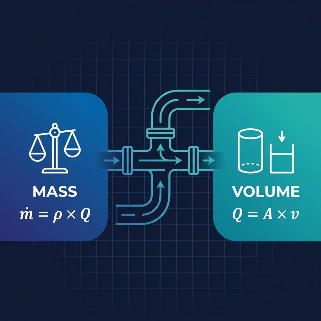
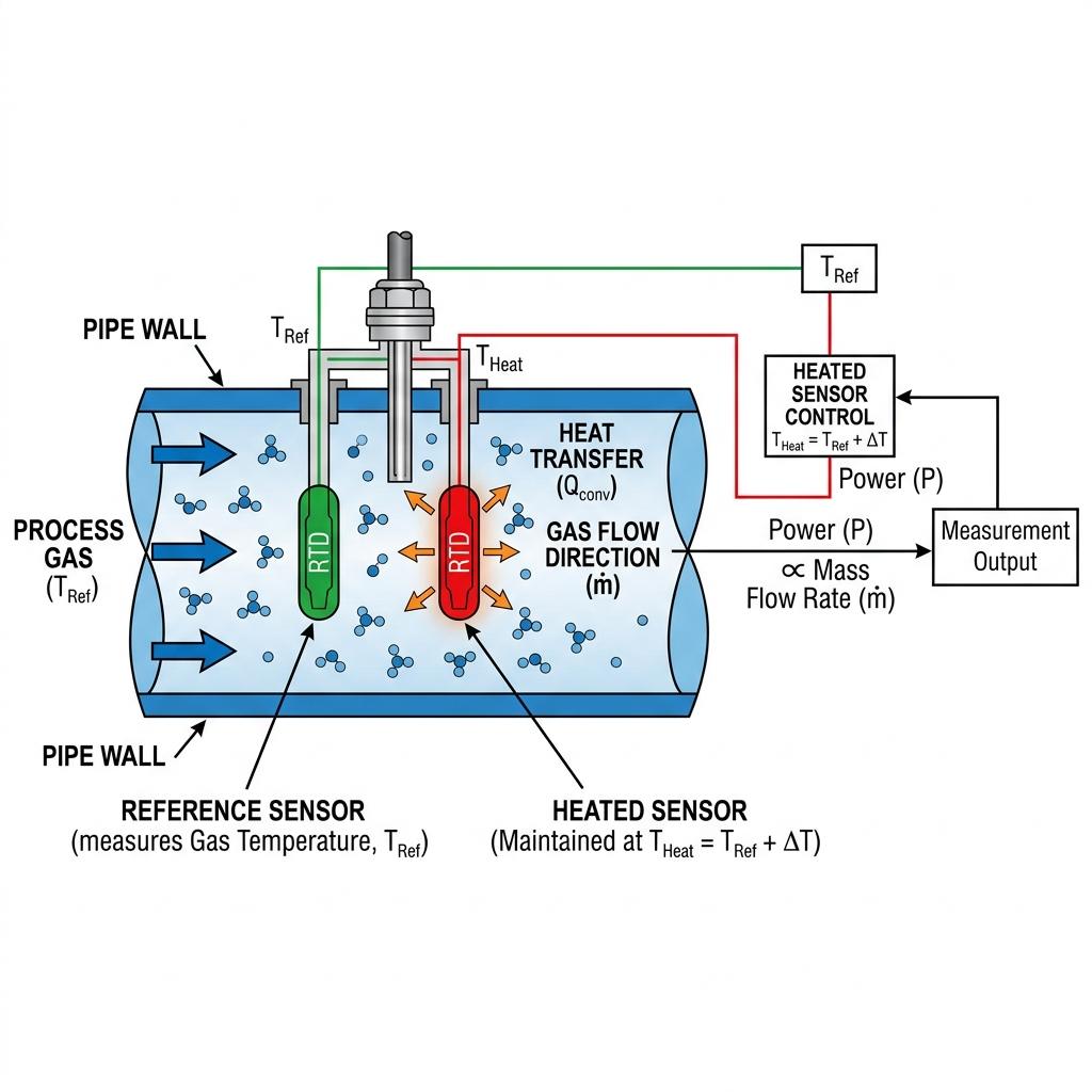
The measuring principle of a thermal mass flow meter is elegant in its simplicity: it measures how much heat a flowing gas carries away from a heated sensor.
Every thermal mass flow meter contains two platinum Resistance Temperature Detectors (RTDs):
- Reference Sensor: Measures the actual temperature of the gas stream.
- Heated Sensor: Maintained at a constant elevated temperature above the reference sensor (constant temperature differential method).
As gas flows past the heated sensor, molecules absorb thermal energy through convective heat transfer, cooling the sensor. The meter’s electronics continuously adjust the electrical power to maintain the constant temperature differential. The greater the gas flow velocity, the more power is required—and this power measurement is directly proportional to the mass flow rate.
This relationship is described by King’s Law (L.V. King, 1914):
Where: Q = heater power, K = balance coefficient, ρ = gas density, V = flow velocity, ΔT = temperature differential.
Why This Matters for Installation
Because the measurement depends on heat transfer from a known surface area, anything that disrupts the flow profile—turbulence, swirl, pulsation—directly degrades accuracy. This is why straight run requirements are not suggestions; they are engineering necessities.
Key Advantages Over Other Flow Technologies
| Feature | Thermal Mass | Vortex | Differential Pressure |
|---|---|---|---|
| Moving parts | None | None | None (but orifice wears) |
| Direct mass measurement | ✅ Yes | ❌ No (volumetric) | ❌ No (inferred) |
| P/T compensation needed | ❌ Not required | ✅ Required | ✅ Required |
| Turndown ratio | 100:1 | 20:1 | 5:1 |
| Operating range (velocity) | 0.1–120 Nm/s | 0.3–80 m/s | Depends on DP |
| Low-flow sensitivity | Excellent (0.1 Nm/s min) | Poor | Poor |
| Compressed air suitability | ✅ Ideal | Good (but needs P/T comp) | Acceptable |
For a broader comparison across flow measurement technologies, see our guide on how different flow meter technologies compare.
Pre-Installation Planning & Application Considerations
Before you open the shipping crate, a few planning decisions will determine whether your thermal mass flow meter delivers ±1% accuracy or ±15% frustration.
Gas Type Considerations
Thermal mass flow meters work with virtually any moisture-free gas except acetylene. Common applications include:
- Compressed air: Energy auditing, leak detection, compressor efficiency monitoring. This is the single most common application we deploy in the field.
- Natural gas: Burner feed control, boiler optimization, custody transfer.
- Flare gas: Environmental compliance monitoring.
- Process gases: Nitrogen, oxygen, CO₂, hydrogen, biogas, and mixed gases.
Each gas has a unique conversion coefficient. If your meter was factory-calibrated on air but you’re measuring natural gas, you must verify that the correct gas density and conversion factor are programmed into the instrument. We once spent two days troubleshooting a “broken” meter at a Zhejiang chemical plant—turned out the conversion coefficient was still set to air instead of nitrogen.
Why Compressed Air Needs Special Attention
Compressed air seems simple, but it presents unique challenges for flow measurement:
- Moisture: Free water acts as a heat sink on the heated sensor, causing false high readings. Always install downstream of air dryers and filters.
- Oil contamination: Oil film on the sensor surface reduces heat transfer, causing readings to drift 3–5% low over weeks.
- Pulsation: Reciprocating compressors generate pressure pulses that can cause velocity fluctuations. A damping factor adjustment (typically 2–5) stabilizes the signal.
If you’re evaluating whether a thermal meter or a vortex meter is better for your compressed air system, our comparison article on vortex flow meters for compressed air provides detailed guidance.
Insertion Type vs. Inline Type
| Parameter | Insertion Type | Inline (Flanged) Type |
|---|---|---|
| Pipe size range | DN40 and above (up to DN4000) | DN10–DN300 |
| Installation | Hot-tap possible (no shutdown) | Requires pipe cut / flange |
| Best for | Large pipes, retrofits | Small pipes, new installations |
| Cost | Lower for large pipes | Lower for small pipes |
| Connection | Ball valve | Flange (customizable) |
For detailed guidance on installing insertion-type meters, see our insertion type flow meter installation guide.
Step-by-Step Thermal Mass Flow Meter Installation Guide
A stable flow field is the prerequisite for accurate measurement. The following steps reflect the procedures we follow across every installation project—from pharmaceutical GMP facilities to steel mill blast furnace gas lines.
1 Pre-Installation Checklist
Before touching any tools:
- ✅ Read the nameplate: confirm flow range, media, pressure rating, ATEX classification (if applicable), and electrical connections.
- ✅ Record the pipe’s inner diameter and wall thickness. You’ll need these exact values for insertion depth calculation.
- ✅ Verify the flow direction arrow on the sensor matches your actual flow direction.
- ✅ Confirm that the mounting location meets flow meter installation requirements.
- ✅ Check sealing materials for compatibility with the process gas.
2 Straight Run Requirements
This is the single most critical installation parameter. Get this wrong, and no amount of calibration will fix your readings.
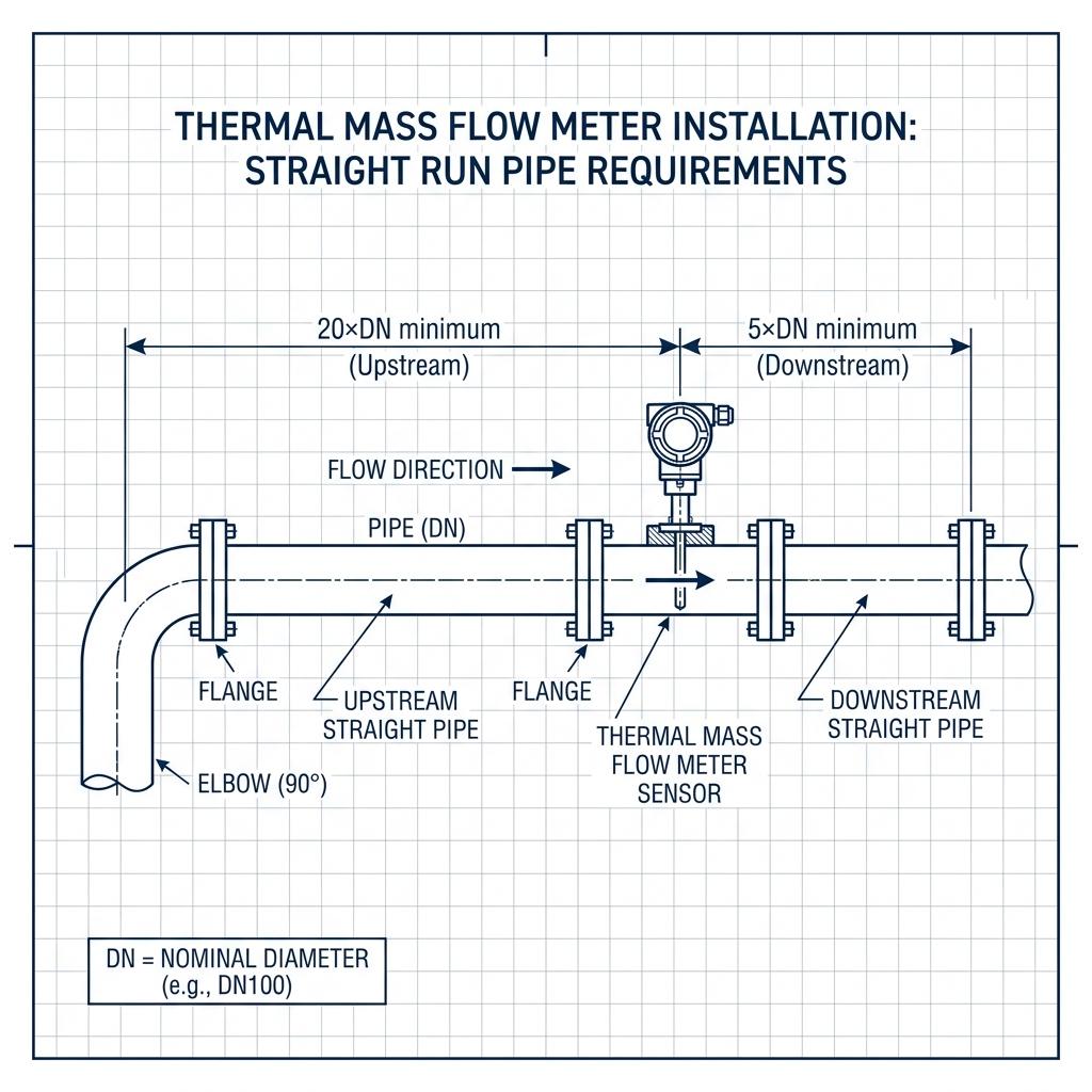
| Upstream Obstruction | Minimum Upstream (×DN) | Minimum Downstream (×DN) |
|---|---|---|
| Single 90° elbow | 20 | 5 |
| Two 90° elbows (same plane) | 25 | 5 |
| Two 90° elbows (different planes) | 40 | 5 |
| Reducer / Expander | 20 | 5 |
| Tee (branch flow) | 20 | 5 |
| Partially open valve | 50 | 5 |
| Flow conditioner installed | 2 + conditioner + 1 | 5 |
Pro tip: Control valves and shut-off valves should always be placed downstream (rare side) of the flow meter. Upstream valves—especially partially open ones—create extreme turbulence that no practical straight run can correct.
3 Mounting Position & Orientation
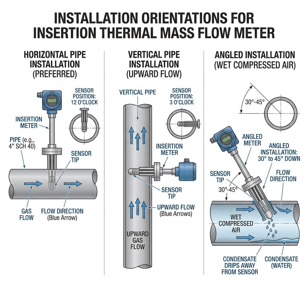
- Horizontal installation: Preferred for most gas applications. Ensure process pressure ≤ 2 MPa.
- Vertical installation: Acceptable when gas flows upward. Process pressure ≤ 2 MPa.
- For wet compressed air: Install the sensor at a 30–45° angle from the top of horizontal pipe to allow condensate to drip away from the sensor tip rather than pooling on it.
- Display orientation: The display can be rotated to 90°, 180°, or 270° for various viewing angles. Never rotate the sensor probe itself—only the display enclosure.
4 Insertion Depth Calculation (Insertion Type)
The sensor tip must reach the pipe centerline for accurate measurement. Calculate insertion depth as:
Installation procedure:
- Place the sensor assembly through the ball valve (do not tighten the nut yet).
- Turn the connecting rod to align the sensor’s flow direction mark with the actual flow direction.
- Using the calibration markings on the connecting rod, set the insertion depth to your calculated value.
- Screw the compression nut firmly. You should feel a smooth, firm resistance—not the spongy feel that indicates a cross-threaded connection.
5 Wiring & Power Connection
| Parameter | Specification |
|---|---|
| Power supply | 24VDC (18–30V range) or 220VAC |
| Operating current | <650 mA |
| Output options | 4–20mA (max load 500Ω), RS-485/HART, Pulse/frequency |
| Alarm output | 2-channel relay, normally open, 3A/30V DC |
| Communication | Modbus RTU (baud: 9600, 8N1 default) |
| Cable | Two-core shielded cable recommended |
6 Commissioning & Warm-Up
- Leak test first: Before applying power, pressurize the system and check all fittings for leaks—especially if handling toxic, explosive, or hazardous gases.
- Apply power: Allow approximately 30 minutes for the sensor to warm up and stabilize. This can be done with or without gas flow.
- Zero-point adjustment: Under zero-flow conditions, if the display doesn’t read zero, adjust the user zero point via the instrument menu (password: 1000).
- Verify initial reading: Compare the meter’s reading against a known reference (e.g., compressor output gauge, or a portable reference meter).
Calibration: Why It Makes or Breaks Your Measurement
You can install a thermal mass flow meter perfectly—correct straight run, proper orientation, ideal insertion depth—and it will still deliver unreliable data if the calibration is inadequate. Thermal flow meter calibration is the process that establishes the mathematical relationship between the electrical power consumed by the heated sensor and the actual mass flow rate of the gas passing through it.
As ISO 14511 (the international standard for thermal mass gas flowmeters) states: “The best practice for calibrating thermal mass flowmeters is to perform an actual gas calibration, and at actual process conditions, when feasible.”
Factory Calibration: What Happens Before Delivery
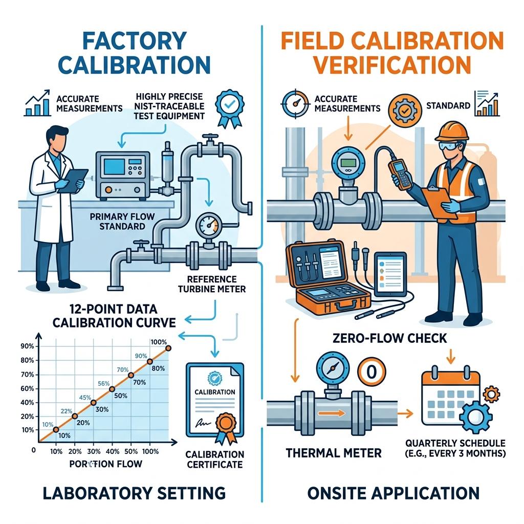
Every quality thermal mass flow meter undergoes factory calibration before shipment. At our NIST-traceable calibration facility, the process includes:
- RTD characterization: Both platinum RTDs are individually calibrated and tested across the specified temperature range to ensure temperature-independent performance.
- Multi-point flow calibration: The sensor is placed in a calibrated test section, and a known quantity of gas is flowed through the pipe. This measurement is repeated at minimum 12 data points across the full operating range.
- Curve fitting: A fifth-order polynomial equation is applied to the calibration data and loaded into the instrument’s firmware.
- Zero-flow characterization: A dedicated zero-flow data point is recorded using a zeroing chamber—this is critical for accurate low-flow measurements.
The actual flow rates during calibration are verified using high-precision turbine flow meters with pressure and temperature correction (uncertainty: 0.5% of reading). For lower flow rates, a Bell Prover with equivalent uncertainty is used as the reference standard.
Actual Gas Calibration vs. Air Equivalency—The Critical Difference
This is the single most important decision in mass flow meter calibration, and the one most commonly gotten wrong.
| Calibration Method | Actual Gas | Air Equivalency (Simulated) |
|---|---|---|
| Process | Flows the specific gas at operating conditions | Flows air, applies theoretical correction factor |
| Accuracy | ±1.0% achievable | ±10% to ±100% for non-air gases |
| ISO 14511 recommendation | ✅ Best practice | ⚠️ “Limited range of applications” |
| Cost | Higher (requires gas infrastructure) | Lower |
| When acceptable | All applications | Only for air/N₂ at ambient conditions |
In-Situ Calibration Verification
Between factory recalibrations, you should perform in-situ verification quarterly. The calibration process in the field involves:
- Zero-flow check: Isolate the meter from flow (close upstream valve). After 5 minutes of stabilization, the meter should read zero ±0.2% of full scale. If not, perform a user zero-point adjustment.
- Comparison check: Install a portable reference meter upstream or downstream and compare readings at 3 flow points (25%, 50%, 75% of range). Deviation >2% warrants a factory recalibration.
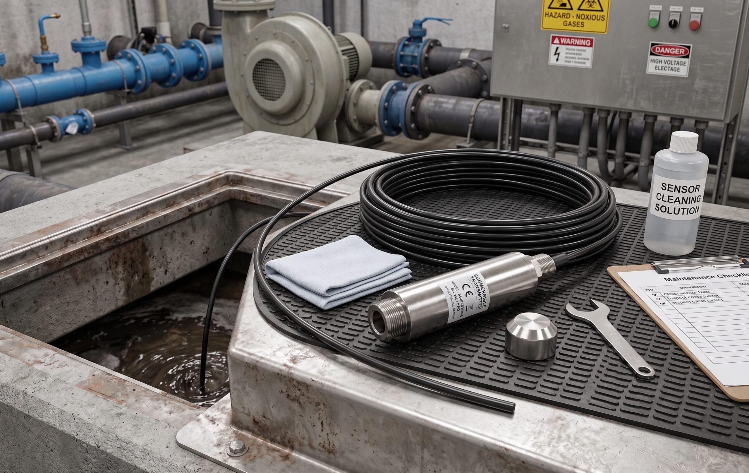
- Sensor inspection: If you can safely remove the insertion probe, visually inspect the sensor tip. Oil film, particulate buildup, or corrosion are common causes of drift.
Recommended Calibration Intervals
| Application Environment | Recommended Interval | Rationale |
|---|---|---|
| Clean, dry gas (compressed air after dryer) | 12 months | Standard practice |
| Wet or dirty gas (biogas, landfill gas) | 6 months | Accelerated sensor fouling |
| Corrosive gas (SO₂, H₂S) | 6 months | Sensor coating degradation |
| High-temperature applications (>100°C) | 12 months (with quarterly verification) | Thermal stress on RTDs |
| Custody transfer / billing | 6–12 months (per contract) | Regulatory compliance |
For more on how often flow meters need calibration across different technologies, see our detailed comparison.
Troubleshooting Common Issues
Before any hardware repair, first verify: power supply is correct, wiring matches the terminal diagram, straight run requirements are met, flow direction matches the sensor arrow, and no pipe leaks exist. These five checks resolve 80% of the problems we encounter in the field.
| Symptom | Possible Cause | Solution |
|---|---|---|
| Velocity anomaly / fluctuation | • Irregular or turbulent flow • No flow conditioner upstream • Incorrect grounding | • Verify straight run per Chapter 6.2 • Install flow conditioner if space limited • Check wiring and ground connection |
| Reading too high | • Sensor direction reversed • Moisture on sensor (compressed air) • Incorrect gas density/conversion coefficient | • Check flow direction arrow • Install dryer/filter upstream • Verify gas type setting in menu |
| Reading too low | • Oil film on sensor tip • Incorrect insertion depth • Sensor fouling (particulates) | • Clean sensor with isopropyl alcohol • Recalculate and verify depth with caliper • Clean or replace sensor |
| No response / zero reading | • No power supply • Gas contains water • Signal cut-off set too high • Actual flow below minimum range | • Verify power (18–30VDC) • Install inline dryer • Reduce signal cut-off via keyboard • Check span setting or contact factory |
| 4–20mA output drift | • Analog output not calibrated • Cable interference | • Calibrate zero (4mA) and span (20mA) using multimeter • Use shielded cable |
| Zero offset (reads flow when no flow) | • User zero point needs adjustment • Ambient temperature fluctuation | • Menu → Settings → User Zero Point: adjust to match no-flow condition • Allow 30+ min warm-up |
| Display shows error code | • Sensor element failure • PCB component failure | • Return to manufacturer for repair |
Technical Specifications: Soaring Thermal Gas Mass Flow Meter
The following specifications are from our current production thermal gas mass flow meter, available in both insertion (plug-in) and inline (flanged) configurations.
| Parameter | Specification |
|---|---|
| Applicable media | Moisture-free gas (except acetylene gas) |
| Accuracy | ±1.0%, ±1.5% |
| Velocity range | (0.1–120) Nm/s |
| Turndown ratio | 100:1 |
| Medium temperature | (-20 to 120)°C |
| Ambient temperature | (-20 to 50)°C |
| Working pressure | 2.5 MPa / 4.0 MPa |
| Responding speed | ≤1 second |
| Power supply | 24VDC / 220VAC |
| Output | RS-485/HART; 4–20mA analog; Pulse/frequency |
| Alarm output | Relay dry contact, up to 2 channels |
| Pipe diameter (insertion) | DN40 and above |
| Pipe diameter (inline) | DN10–DN300 |
| Pipe material | Carbon steel, stainless steel |
| Protection class | IP65 |
| Explosion-proof grade | Exd II ct4 |
| Process connection | Ball valve / Flange (customizable) |
| Electrical interface | M20×1.5 |
| Display | Four-line LCD (mass flow, volume flow, totalizer, velocity) |
Key Applications per Product Catalog
- Gas flow measurement in iron & steel plants and coking plants
- Boiler air flow measurement (secondary air volume)
- Flue gas flow measurement from chimneys
- Compressed air flow measurement
- Natural gas, coal gas, liquefied gas, flare gas, hydrogen flow measurement
- Gas flow in cement, cigarette, and glass factory production processes
Common Applications & Real-World Case Studies
Compressed Air: The #1 Application
According to the U.S. Department of Energy (DOE), compressed air systems typically waste 20–30% of their output through leaks. Thermal mass flow meters are the preferred tool for quantifying this waste because they can detect very low flows (as low as 0.1 Nm/s) without requiring pressure or temperature compensation.
Common compressed air monitoring use cases:
- Leak quantification: Measure airflow during non-production hours to establish baseline leakage rates.
- Compressor efficiency: Monitor output vs. power consumption per compressor unit.
- Zone-based submetering: Allocate compressed air costs to individual production lines or buildings.
We installed 6 insertion-type thermal mass flow meters across the compressed air distribution network of a pharmaceutical GMP facility. Each meter was positioned downstream of the zone air dryer, with 25×DN upstream straight run from the nearest elbow.
By monitoring zone-by-zone consumption during non-production hours (weekends and night shifts), the plant identified a 28% leakage rate—primarily from aging quick-disconnect fittings in the packaging area and micro-cracks in 15-year-old galvanized distribution headers.
Results after leak repair:
- Leakage rate reduced from 28% to 8%
- Annual compressed air energy costs dropped by ¥180,000 (≈$25,000)
- One compressor unit was taken offline during off-peak shifts, extending maintenance intervals
- ROI on the 6-meter monitoring system: 14 months
Other High-Value Applications
- Natural gas: Burner feed control, boiler optimization, fuel gas distribution metering.
- Flare gas: Environmental compliance monitoring—mandatory in many jurisdictions for emissions reporting.
- Biogas: Digestor output monitoring at wastewater treatment plants. Note: biogas applications require more frequent calibration (6-month intervals) due to moisture and H₂S content.
For insights on how temperature affects flow measurement accuracy across these applications, see our technical deep dive.
Frequently Asked Questions
What is the accuracy of a thermal mass flow meter?
A properly installed and calibrated thermal mass flow meter typically achieves ±1.0% to ±1.5% accuracy. This requires: correct straight run lengths (20×DN upstream, 5×DN downstream), proper sensor alignment with the flow direction, dry and clean gas, and NIST-traceable calibration with actual gas rather than air equivalency. Operating at less than 10% of the meter’s full-scale range typically increases uncertainty.
How often should a thermal mass flow meter be calibrated?
Most manufacturers recommend annual recalibration. Meters in harsh environments (high moisture, particulate contamination, or corrosive gases) may require recalibration every 6 months. Between factory calibrations, perform quarterly in-situ calibration verification—a simple zero-flow check that takes 10 minutes and can detect drift before it affects your process data. Learn more about flow meter calibration standards.
Can I install a thermal mass flow meter in a vertical pipe?
Yes. Both horizontal and vertical installations are acceptable, provided the process pressure does not exceed 2 MPa. For vertical pipes, gas should flow upward to ensure a full-pipe condition. In applications where moisture is present (e.g., compressed air without adequate drying), horizontal installation with the sensor at a 30–45° angle is preferred to prevent condensate from pooling on the heated sensor.
Does a thermal mass flow meter require pressure and temperature compensation?
No. This is one of the key advantages of thermal mass flow technology. Because the measuring principle is based on heat transfer from the heated sensor to gas molecules, the measurement inherently captures mass flow—which is independent of pressure and temperature variations. The constant temperature differential method means the electronics automatically compensate for any ambient temperature fluctuation, eliminating the need for external P/T compensation.
What is the minimum straight run required for a thermal flow meter?
The minimum is 20×DN upstream and 5×DN downstream from the nearest flow disturbance. For light gases (hydrogen, helium), double the upstream requirement to 40×DN. If insufficient space exists, a flow conditioning plate can be installed upstream—requiring approximately 3×DN total (2 before the conditioner, 1 after). For detailed guidance on straight-run requirements across multiple flow meter types, see our critical straight run requirements guide.
What is the difference between actual gas calibration and air equivalency?
Actual gas calibration flows the specific gas or gas mixture through the meter during the calibration procedures, capturing the true thermal heat dissipation characteristics. Air equivalency uses air as a surrogate fluid and applies a theoretical correction factor. ISO 14511, Section 8 confirms that actual gas calibration is the best practice, because equivalency methods can introduce errors of up to ±100% for certain gases. The nonlinear relationship between thermal conductivity, specific heat, viscosity, and density across a wide turndown ratio cannot be captured by a single linear correction. For compressed air or nitrogen, air-based calibration is acceptable since the properties are nearly identical.
How long does a thermal mass flow meter last?
With proper installation, clean gas conditions, and regular flow meter maintenance, a thermal mass flow meter can last 15–20 years. The sensor contains no moving parts, eliminating mechanical wear. The primary lifespan factors are: gas cleanliness (particulates can damage sensor coatings), moisture exposure (corrosion risk to RTD elements), and operating within the specified temperature range of -20°C to 120°C for medium temperature (per product specifications).
Conclusion: 5 Key Takeaways
- Straight run is non-negotiable: 20×DN upstream, 5×DN downstream. Double for light gases. No exceptions.
- Install downstream of treatment: For compressed air, always position the meter after dryers and filters. Moisture destroys measurement accuracy.
- Demand actual gas calibration: ISO 14511 confirms it’s the gold standard. Air equivalency is acceptable only for air and nitrogen at ambient conditions.
- Commission properly: Allow 30+ minutes for warm-up (45 minutes in cold environments). Perform zero-point adjustment under verified no-flow conditions.
- Verify quarterly, recalibrate annually: A 10-minute zero-flow check catches drift before it becomes a process problem.
Need Help With Your Thermal Mass Flow Meter Installation?
Our engineering team has installed and calibrated thermal mass flow meters in 500+ industrial facilities. Whether you need pre-installation pipe assessment, custom calibration for specialty gases, or on-site commissioning support—we’re here to help.
📧 Contact Our Engineering Team
Shanghai Soaring Instrument Technology Co., Ltd. | [email protected] | +86-13585991410
Related Articles
- How Do Different Flow Meter Technologies Compare in Performance?
- Critical Straight Run Requirements for Flow Meters
- What You Need to Know About Flow Meter Calibration
- What Is the Standard for Calibration of Flowmeters?
- How Often Do Flow Meters Need to Be Calibrated?
- Key Requirements for Flow Meter Installation
- How to Install an Insertion Type Flow Meter
- Vortex Flow Meters for Compressed Air Measurement
- Best Practices for Flow Meter Maintenance
- Effect of Temperature on Flow Measurement