Every ultrasonic flow meter will eventually drift. It might take six months, it might take two years — but the transit-time signal that was perfectly zeroed on installation day will gradually shift as pipe conditions change, transducer coupling degrades, or temperature cycles stress the electronics. When your readings start showing 2-3% offset from what your process tells you is right, it’s time to calibrate.
In our experience commissioning and maintaining clamp-on ultrasonic meters across chemical plants, water utilities, and HVAC systems, we’ve found that most “accuracy problems” aren’t actually calibration issues at all — they’re installation problems masquerading as drift. That’s why this guide starts with a pre-calibration checklist before walking you through the actual calibration procedures.
Quick Answer: Ultrasonic flow meter calibration involves verifying and adjusting the meter’s zero point and K-factor against a known reference standard. For clamp-on meters, start by checking transducer coupling and signal strength before assuming the meter needs recalibration. Factory calibration uses gravimetric or piston prover methods; field verification typically uses a portable ultrasonic meter or master meter as reference.
If you’re unfamiliar with how ultrasonic meters measure flow, our guide to ultrasonic flow meter technology explains the transit-time principle in detail.
What Is Flow Meter Calibration?
Calibration is the process of comparing a measuring instrument’s output against a known, traceable reference standard — and adjusting the instrument to minimize the difference between its reading and the “true” value.
For ultrasonic flow meters specifically, calibration involves two primary adjustments:
| Parameter | What It Does | When It Drifts |
|---|---|---|
| Zero Point | Sets the baseline reading when flow = 0 | Electronic noise, temperature drift, transducer aging |
| K-Factor (Span) | Converts raw transit-time signals into volumetric flow | Pipe wall changes, fluid property shifts, transducer repositioning |
Important distinction: Calibration is not the same as verification. Verification confirms that the meter is reading within its stated accuracy (±1.0% for our wall-mount clamp-on models). Calibration actually adjusts the meter’s internal parameters to bring it back into specification.
Note: “Zero cut” (low-flow cutoff) is a software setting that forces the display to zero below a threshold velocity — it’s a noise filter, not a calibration adjustment. Don’t confuse the two.
Before You Calibrate: Pre-Calibration Checklist
Based on our field service experience, roughly 60-70% of “calibration requests” we receive are actually installation or signal quality issues. Before spending time and money on formal calibration, run through this checklist:
Signal Quality Verification
| Check | What to Look For | Action if Failed |
|---|---|---|
| Signal strength | > 60% on display (varies by manufacturer) | Reapply couplant, clean pipe surface, realign transducers |
| Transit time ratio (Up/Down) | Should be close to 1.000 (±0.002) | Indicates misalignment — reposition transducers |
| Signal quality indicator | No frequent error codes or “low signal” warnings | Check for air bubbles, pipe deposits, or incorrect pipe parameters |
Installation Geometry
- Straight pipe runs: Verify minimum 10D upstream / 5D downstream from disturbances (bends, valves, pumps)
- Transducer spacing: Confirm the programmed pipe OD, wall thickness, and liner thickness match reality — measure with calipers, don’t trust nameplate data on old pipes
- Mounting method: V-method for DN50–DN300, Z-method for DN300+ or heavy-walled pipes
Pipe Condition Assessment
Here’s a field tip that saves us hours of troubleshooting: tap the pipe with a small hammer near the transducer location. If you hear a dull thud instead of a clear ring, there’s likely significant internal scale buildup. This changes the effective wall thickness and acoustic path — and no amount of zero calibration will fix an incorrect wall thickness parameter.
- Check for internal corrosion or scale (add 2-4 mm to wall thickness if suspected)
- Verify pipe material matches the programmed value (carbon steel vs. stainless vs. cast iron sound very different)
- Ensure the pipe is completely full at the measurement point
If all checks pass and readings are still off by more than ±2% of expected flow, proceed to calibration.
Calibration Methods Compared
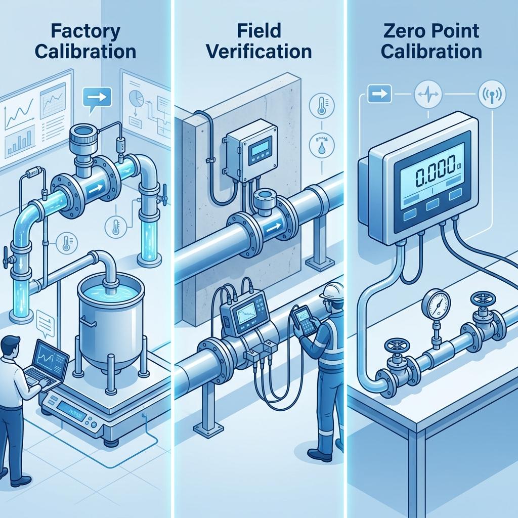
There are three fundamental approaches to ultrasonic flow meter calibration, each with different accuracy levels and practical trade-offs:
| Method | Accuracy | Cost | Downtime | Best For |
|---|---|---|---|---|
| Factory (gravimetric/prover) | ±0.1–0.2% | High | Days (meter removed) | Custody transfer, initial commissioning |
| Field verification (master meter) | ±0.5–1.0% | Medium | Hours | Annual checks, process control |
| Self-verification (portable reference) | ±1.0–2.0% | Low | Minutes | Routine monitoring, troubleshooting |
Factory (Laboratory) Calibration
Factory calibration is the gold standard. The meter is installed in a controlled flow loop where fluid temperature, pressure, and flow rate are precisely regulated.
Gravimetric Method (Weigh Tank)
1. Fluid flows through the meter into a collection tank on a precision scale
2. The mass of collected fluid over a measured time interval gives the “true” flow rate
3. The meter’s reading is compared and adjusted
4. Typical uncertainty: ±0.1%
Piston Prover
1. A precision-machined piston displaces a known volume of fluid
2. The meter’s pulse output is compared to the displaced volume
3. Multiple runs at different flow rates generate a linearity curve
4. Typical uncertainty: ±0.15%
Master Meter Comparison
1. A pre-calibrated, high-accuracy reference meter (typically a Coriolis meter at ±0.1%) is installed in series
2. Both meters read the same flow simultaneously
3. Discrepancies are used to adjust the unit under test
4. Typical uncertainty: ±0.2–0.3%
Factory calibration produces a multi-point calibration certificate with traceability to national standards (NIST in the US, PTB in Germany, NIM in China). This certificate documents the meter’s performance across its full flow range and provides the legal basis for custody transfer applications.
Field (In-Situ) Verification
Field verification confirms meter performance without removing it from the pipeline — critical for processes that cannot be shut down.
Using a Portable Ultrasonic as Reference:
This is where our portable ultrasonic flow meter becomes a powerful calibration tool. By clamping a portable meter on the same pipe section (or as close as possible to the installed wall-mount unit), you can compare readings in real time.
Steps:
1. Install portable transducers on the same pipe, downstream of the wall-mount meter (maintaining required straight runs)
2. Allow both meters to stabilize for 5-10 minutes at steady flow
3. Compare readings across at least 3 different flow rates (low / mid / high)
4. If deviation is consistent (e.g., wall-mount reads 2.5% high at all rates), adjust the K-factor
5. If deviation varies with flow rate, the issue is likely installation-related, not calibration
Using an Inline Master Meter:
For higher accuracy field verification, a pre-calibrated electromagnetic or Coriolis meter can be temporarily installed in series. This requires a brief process shutdown for installation but provides ±0.5% reference accuracy.
When to Choose Which Method
| Scenario | Recommended Method |
|---|---|
| New installation commissioning | Factory calibration (before shipping) |
| Annual compliance verification | Field verification with portable reference |
| Custody transfer / billing meters | Factory calibration every 12 months |
| Suspected drift after maintenance | Self-verification with portable meter first |
| Regulatory audit preparation | Factory calibration with ISO 17025 certificate |
Step-by-Step: Zero Point Calibration
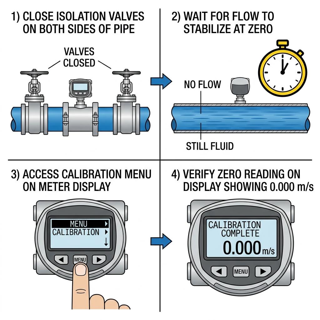
Zero point calibration eliminates the baseline offset that accumulates from electronic noise, temperature drift, and acoustic interference. This is the most common field calibration procedure.
Prerequisites
- The pipe must be completely full of process fluid
- Flow must be completely stopped (close isolation valves on both sides of the meter)
- Allow the system to stabilize for at least 2 minutes after valve closure (thermal convection currents need time to settle)
- Verify no leaking valves upstream (even a small leak creates flow)
Procedure
Confirm zero-flow conditions: Watch the velocity display for 30 seconds. It should fluctuate randomly around zero (±0.01 m/s). If it shows a consistent non-zero value, you likely have a leaking valve.
Access the calibration menu: Navigate to Setup → Calibration → Zero Point (exact menu path varies by manufacturer and firmware version)
Execute auto-zero: Select “Start Zero Calibration” or “Auto-Zero”. The meter will:
- Sample the transit-time signals for 30-60 seconds
- Calculate the average offset
Store the new zero reference
Verify: After completion, the display should read 0.000 m/s (or within ±0.003 m/s). If it doesn’t stabilize near zero, check for:
- Trapped air bubbles near transducers
- External vibration sources (nearby pumps, compressors)
Thermal convection in the pipe (hot fluid rises, cold sinks)
Document: Record the “as-found” zero offset (before adjustment) and “as-left” value (after adjustment) in your calibration log.
Field Tip: We’ve encountered situations where the zero wouldn’t stabilize because the pipe ran next to a vibrating compressor. The solution was to perform the zero calibration during a scheduled compressor shutdown, or to add vibration isolation pads under the transducers.
Step-by-Step: K-Factor / Span Adjustment
The K-factor (also called velocity coefficient or span factor) corrects the relationship between the measured transit-time difference and the actual flow velocity. If your meter consistently reads high or low by a fixed percentage across all flow rates, the K-factor needs adjustment.
When K-Factor Adjustment Is Needed
- Meter consistently reads 3-5% high or low at all flow rates
- New transducers installed on an existing pipe
- Pipe wall thickness has changed significantly (corrosion/scaling)
- Fluid acoustic properties have changed (different fluid, temperature shift)
Procedure
- Establish a reference flow: Use one of these methods:
- Portable ultrasonic meter (easiest for clamp-on systems)
- Bucket-and-stopwatch (for open discharge, small flow rates)
- Pump curve verification (known pump at known operating point)
Process mass balance (comparing inlet vs. outlet over time)
Record readings at multiple flow rates:
| Test Point | Reference Flow (m³/h) | Meter Reading (m³/h) | Error (%) |
|---|---|---|---|
| Low (25% of max) | ___ | ___ | ___ |
| Mid (50% of max) | ___ | ___ | ___ |
| High (75% of max) | ___ | ___ | ___ |
- Calculate correction factor:
K_new = K_current × (Reference Flow / Meter Reading)
Example: If the meter reads 102.5 m³/h when the reference shows 100.0 m³/h, and K_current = 1.000:
K_new = 1.000 × (100.0 / 102.5) = 0.9756
Enter new K-factor: Navigate to Setup → Calibration → K-Factor and enter the calculated value.
Verify: Re-run the comparison at each flow rate. All readings should now be within ±1.0% of the reference.
Document: Record K_old, K_new, and verification readings.
Important: When NOT to Adjust K-Factor
If the error is not consistent across flow rates (e.g., -2% at low flow but +3% at high flow), the problem is not the K-factor. Non-linear errors typically indicate:
– Incorrect pipe parameters (OD, wall thickness, material)
– Flow profile distortion (insufficient straight runs)
– Transducer misalignment
– Two-phase flow conditions (entrained air)
In these cases, fix the installation issue first — don’t try to “calibrate away” an installation problem.
Calibration Frequency: How Often Should You Calibrate?
There is no universal answer — calibration frequency depends on application criticality, operating conditions, and regulatory requirements. Use this decision framework:
| Application | Risk Level | Recommended Interval | Justification |
|---|---|---|---|
| Custody transfer / billing | Critical | 3–6 months | Financial exposure; contractual/regulatory mandate |
| Process control (chemical/pharma) | High | 6–12 months | Product quality; batch consistency |
| Utilities monitoring | Medium | 12 months | Energy auditing; operational efficiency |
| HVAC / building management | Medium | 12–18 months | Energy monitoring; lower consequence of drift |
| Non-critical general monitoring | Low | 18–24 months | Trending only; absolute accuracy less important |
Extending Calibration Intervals
If your meter shows consistent “as-found” readings within specification across multiple calibration cycles, you have evidence to justify extending the interval. Conversely, if “as-found” readings consistently exceed your tolerance, shorten the interval.
Best practice: Plot the “as-found” deviation at each calibration against time. If the drift rate is predictable and slow, you can scientifically justify longer intervals — and defend this to auditors.
Clamp-On Ultrasonic Meters: Special Calibration Considerations
Clamp-on meters have unique characteristics that affect calibration differently from inline meters:
Why Clamp-On Meters Drift Differently
| Factor | Inline Meter | Clamp-On Meter |
|---|---|---|
| Wetted parts degradation | Yes (fouling/corrosion affects bore) | No (transducers are external) |
| Coupling degradation | N/A | Yes — couplant dries out over time |
| Pipe wall changes | Minimal (meter has its own bore) | Significant — corrosion/scale changes acoustic path |
| Transducer alignment | Factory-fixed | Can shift — vibration, thermal cycling |
Clamp-On Specific Maintenance Schedule
| Item | Frequency | Procedure |
|---|---|---|
| Couplant inspection | Every 6 months | Check for drying/cracking; reapply if degraded |
| Transducer torque check | Every 12 months | Verify mounting hardware hasn’t loosened |
| Signal strength check | Every 6 months | Compare to installation baseline; >20% drop = action needed |
| Zero verification | Every 12 months | During scheduled process shutdown |
| Full calibration | Per application table above | Factory or field method |
Using a Portable to Verify a Wall-Mount
One of the most practical field verification methods for our customers is using our portable ultrasonic flow meter to spot-check the wall-mount installation:
- Clamp the portable transducers on the same pipe, 10-20D downstream of the wall-mount
- Set identical pipe parameters (OD, wall thickness, material, fluid type)
- Compare readings at current operating flow
- Agreement within ±2% confirms the wall-mount is performing correctly
- If deviation > 3%, investigate further before adjusting
This takes about 15 minutes and requires no process interruption — making it ideal for quarterly confidence checks between formal calibrations.
Standards & Traceability
For calibration to be legally and commercially defensible, it must be traceable to recognized national or international standards:
| Standard | Scope | When Required |
|---|---|---|
| ISO/IEC 17025 | Laboratory calibration competence | Any formal calibration certificate |
| ISO 9001 | Quality management system | Manufacturing & service organizations |
| AGA Report 9 | Multipath ultrasonic meters for gas | Natural gas custody transfer |
| API MPMS Chapter 5.8 | Ultrasonic meters for petroleum | Oil & gas custody transfer |
| ISO 17089-1 | Ultrasonic meters for gas flow | Gas measurement applications |
| NIST traceability | National measurement standard (US) | Any measurement requiring legal traceability |
What “NIST-Traceable” Actually Means
A calibration is “NIST-traceable” when there is an unbroken chain of comparisons linking your meter’s calibration to the national standard:
Your meter → Master meter → Lab reference → NIST primary standard
Each link in this chain has documented measurement uncertainty. The total uncertainty of your meter’s calibration is the combined uncertainty of all links — which is why laboratory calibration (fewer links, lower individual uncertainties) is always more accurate than field verification (more links, higher uncertainties).
Common Calibration Mistakes (and How to Avoid Them)
Based on the calibration issues we see most frequently in the field:
| Mistake | Consequence | Prevention |
|---|---|---|
| Calibrating with flow still present | Zero offset becomes embedded in normal readings | Close both isolation valves; verify zero velocity |
| Ignoring pipe condition changes | K-factor adjustment masks the real problem | Always check signal strength trend before adjusting |
| Using uncalibrated reference meter | Transferring errors from reference to your meter | Ensure reference meter has current calibration certificate |
| Adjusting K-factor for non-linear error | Creates new errors at other flow rates | K-factor only for consistent % error across all rates |
| Over-frequent calibration | Unnecessary cost and process disruption | Use trend data to justify interval decisions |
| Skipping documentation | No audit trail; can’t detect drift trends | Always record as-found and as-left values |
FAQ: Ultrasonic Flow Meter Calibration
How do I know if my ultrasonic flow meter needs calibration?
Look for these indicators: (1) consistent offset from expected values based on process mass balance, (2) gradual drift in the same direction over weeks/months, (3) signal strength dropping below 60% of installation baseline, (4) zero reading when flow is clearly present, or (5) regulatory schedule requires it regardless of performance. Always run the pre-calibration checklist first — many apparent calibration issues are actually installation problems.
Can I calibrate a clamp-on ultrasonic flow meter without stopping flow?
You cannot perform zero calibration without stopping flow — the meter needs true zero-flow conditions to establish its baseline. However, you can perform K-factor/span verification while flow is running by comparing against a portable reference meter or inline master meter. This is one of the major practical advantages of clamp-on technology: the transducers don’t need to be removed from the pipe for any calibration procedure.
What is the difference between wet calibration and dry calibration?
Wet calibration involves flowing actual fluid through the meter and comparing its output against a reference standard — this is “real” calibration. Dry calibration (also called “electronics calibration” or “bench check”) tests only the electronic signal processing by injecting simulated transit-time signals into the electronics. Dry calibration verifies the electronics are working correctly but cannot account for acoustic path effects, pipe condition, or transducer coupling quality. For clamp-on meters, wet calibration (in-situ or laboratory) is always preferred.
How accurate is field calibration compared to factory calibration?
Factory laboratory calibration typically achieves ±0.1–0.2% uncertainty against primary standards. Field verification using a portable ultrasonic meter as reference achieves ±1.0–2.0% uncertainty (limited by the portable meter’s own accuracy and installation conditions). Field verification with a high-accuracy inline master meter (Coriolis or electromagnetic) can achieve ±0.5%. For process control applications, field verification is usually sufficient. For custody transfer or billing, factory calibration is required.
Do ultrasonic flow meters need calibration more or less often than other meter types?
Generally less often. Because ultrasonic meters (especially clamp-on) have no moving parts and no wetted elements that wear or foul, they exhibit less mechanical drift than turbine meters, vortex meters, or DP (orifice plate) meters. The primary drift mechanisms for ultrasonic meters are electronic aging and (for clamp-on) coupling degradation — both of which are slow processes. However, if pipe internal conditions change significantly (heavy scaling, corrosion), calibration frequency should increase regardless of meter type.
What does a calibration certificate include?
A proper calibration certificate (per ISO/IEC 17025) includes: (1) unique certificate identification number, (2) date of calibration, (3) meter identification (serial number, model), (4) reference standard used (with its own calibration traceability), (5) environmental conditions during test, (6) test results at multiple flow points (typically 5-10 points across the range), (7) measurement uncertainty statement, (8) as-found and as-left data, (9) pass/fail determination against stated specifications, and (10) signatures of calibration technician and authorized reviewer.
Conclusion
Calibrating an ultrasonic flow meter is straightforward — but only if you approach it systematically. The key takeaways:
- Check installation first — Most “calibration problems” are actually signal quality or pipe condition issues
- Zero calibration requires zero flow — No shortcuts here; close both isolation valves
- K-factor fixes constant percentage errors — If the error varies with flow rate, fix the installation instead
- Match calibration method to application — Custody transfer needs factory calibration; process monitoring can use field verification
- Document everything — As-found/as-left records are your proof of due diligence and your tool for optimizing calibration intervals
For clamp-on ultrasonic meters specifically, regular couplant inspection and signal strength monitoring are just as important as periodic calibration — and much easier to perform.
Need Help With Ultrasonic Flow Meter Calibration?
Our engineering team at Soaring Instrument specializes in deploying and maintaining ultrasonic flow measurement systems across diverse industrial applications. Whether you need guidance on calibration procedures, help troubleshooting accuracy issues, or a portable ultrasonic meter for field verification, we’re here to help.
👉 Contact our team for a free consultation
📧 Or email us directly at [email protected]
Related Articles
- How Does an Ultrasonic Flow Meter Work: Understanding the Technology
- How Accurate Are Ultrasonic Flow Meters?
- Clamp-On Ultrasonic Flow Meter: The Complete Guide
- How to Install a Clamp-On Ultrasonic Flow Meter
- What’s the Best Way to Maintain Your Ultrasonic Flow Meter?
- Portable Ultrasonic Flow Meter: The Ultimate Buyer’s Guide
- What Are the Advantages and Disadvantages of Ultrasonic Flow Meters?
- Ultrasonic Flow Meter Pressure Drop: Why It’s Practically Zero