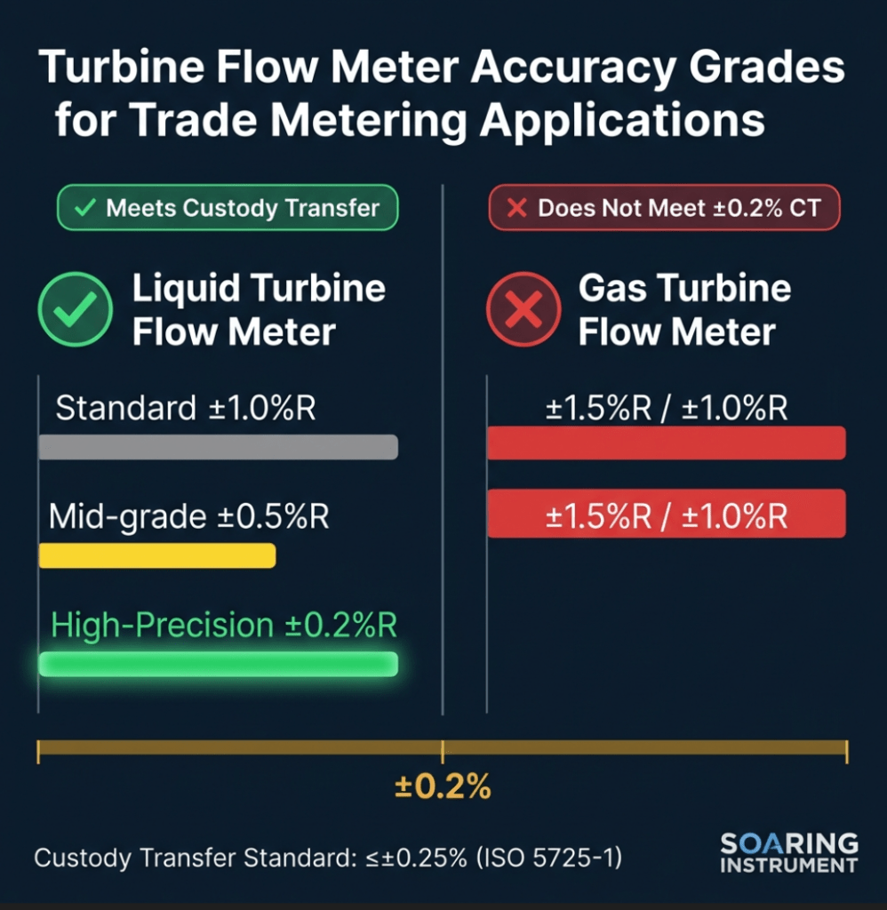
Figure 1: Liquid vs. Gas Turbine Flow Meter Accuracy Comparison — Only the High-Precision Liquid Turbine meets the ±0.2% custody transfer threshold
In our 15+ years working with petrochemical and oil & gas clients, I’ve seen one question come up more than any other during meter selection: "Can this turbine flow meter actually hold ±0.2% over the full service life — or just on the day it leaves the factory?"
It’s a fair question. In custody transfer, where a single percentage point error on a 10,000-barrel-per-day crude oil pipeline translates to real financial loss, the gap between claimed and delivered accuracy is not academic — it’s contractual.
Quick Answer: Yes — liquid turbine flow meters with a high-precision grade (Accuracy Class ±0.2%R) can meet custody transfer requirements when properly calibrated and installed. However, standard gas turbine flow meters (typically ±1.0%–±1.5%R) do not meet the ±0.2% threshold without significant system-level upgrades. Choosing the wrong grade is one of the most costly metering mistakes we see in the field.
For a foundation on how turbine meters work before diving into accuracy, see our guide: Turbine Flow Meter Working Principle: How Does It Operate?
What Does "Turbine Flow Meter Accuracy" Actually Mean?
Flow meter accuracy and flow meter repeatability are two different things — and confusing them is a common and expensive mistake.
| Term | Definition | Typical Expression | Why It Matters |
|---|---|---|---|
| Accuracy | How close the reading is to the true flow rate | ±0.2%R, ±0.5%FS | Determines financial correctness in custody transfer |
| Repeatability | Ability to produce the same reading under identical conditions | ±0.05%–±0.2% | Determines process control reliability |
| Resolution | Smallest detectable increment of flow | e.g., 0.1 L/pulse | Affects low-flow performance |
In custody transfer contexts — where flow measurement is defined by Wikipedia’s custody transfer article as "a metering point where fluid is sold from one party to another" — accuracy is paramount. ISO 5725-1 defines accuracy as "the closeness of agreement between a test result and the accepted reference value," which encompasses both systematic error (bias) and random error.
%R vs. %FS — the number that matters:
- ±0.2%R (of Reading): Error stays proportional to actual flow. At 100 m³/h and at 20 m³/h, the error is ±0.2% of that flow. Better for ranged applications.
- ±0.2%FS (of Full Scale): Error is fixed based on the maximum range. At low flows, this can represent a much larger percentage of the actual reading.
For custody transfer, %R is always preferred because it scales with the actual flow being measured and sold.
Which Products Meet the ±0.2% Precision Threshold?
This is where we must be completely transparent with you. Not all turbine flow meters are created equal.
✅ Liquid Turbine Flow Meter — Meets ±0.2%R
Our Liquid Turbine Flow Meter (model series following JB/T9246-1999) offers three selectable accuracy grades:
| Accuracy Grade | Specification | Suitable For |
|---|---|---|
| Standard | ±1.0%R | General industrial monitoring |
| Mid-grade | ±0.5%R | Process control, HVAC |
| High-precision (Customized) | ±0.2%R | Custody transfer, trade settlement |
Key specifications that enable ±0.2%R:
- Sensor material: 304/316 stainless steel
- Connection: Thread, flange, clamp, wafer
- Repeatability: Short-term repeatability 0.05%–0.2%
- Medium conditions: Kinematic viscosity < 5×10⁻⁶ m²/s at working temperature; clean liquid, no suspended fibers or particles
- Temperature: Medium −20°C to +120°C; ambient −20°C to +60°C
- Output: Pulse signal, 4-20mA, RS485, HART protocol
The preferred flow meter in trade settlement — as stated in our product specification — is the liquid turbine with ±0.2%R specification. This isn’t marketing language; it’s because the physics of the device (single rotating part, clean fluid, stable K-factor) allows it.
Field observation: When we install ±0.2%R liquid turbines for petroleum product custody transfer skids, we always verify that the actual operating viscosity closely matches the calibration viscosity. Even a 10% change in kinematic viscosity can degrade accuracy by 0.3–0.5% — which would exceed the targeted specification.
❌ Gas Turbine Flow Meter — Does NOT Meet ±0.2%R Standard
We need to be direct: our Gas Turbine Flow Meter is specified at:
| Parameter | Value |
|---|---|
| Accuracy | ±1.5%R or ±1.0%R |
| Repeatability | 0.05%–0.2% |
| Turndown ratio | 10:1, 20:1, 30:1 |
| Medium temperature | −10°C to +100°C |
For natural gas measurement in trade contexts — especially for billing — the gas turbine’s accuracy class of ±1% to ±1.5% does not meet the strict ±0.2% requirement without additional system-level compensation. Gas turbines are excellent for flow monitoring and process control in the oil & gas sector, but buyers and sellers requiring custody transfer-grade gas measurement should consider:
- Pairing with a transfer standard and flow computer for K-factor correction
- Considering ultrasonic flowmeters (typically ±0.7%–±1.0%) as an alternative
- Frequent recalibration per AGA Report No. 7 requirements
For a detailed comparison of different meter types for gas applications, see: Which Flow Meter Is Best For Natural Gas Measurement?
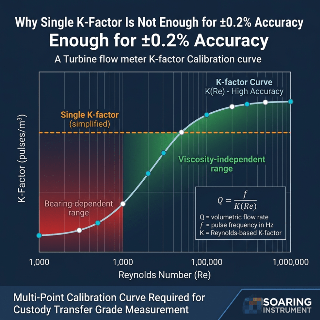
Figure 2: K-Factor Calibration Curve (K vs Reynolds Number) — Multi-point calibration curve required; single K-factor insufficient for custody transfer grade accuracy
How Turbine Flow Meter Calibration Achieves ±0.2% Precision
Reaching — and holding — ±0.2% accuracy over the service life of a turbine flow meter requires a disciplined calibration program. Here is how it works in practice.
The K-Factor and the Calibration Curve
Every turbine flow meter is characterized by its K-Factor: the number of pulses generated per unit volume of fluid. According to NIST’s turbine meter calibration program, a single K-factor is an oversimplification. For high-accuracy work, a flow-dependent K-factor curve (also called a calibration curve or universal viscosity curve) must be stored in the flow computer.
NIST calibrates turbine meters using dimensionless Strouhal (St) and Reynolds (Re) numbers, which collapse multiple viscosity calibration curves into a single "viscosity-independent range." This is why:
- The calibration fluid viscosity must match operating conditions
- The K-factor curve — not a single K value — must be programmed into the flow computer
- Calibration points should span the full operating flow range (typically 10 evenly-spaced points for a single-viscosity calibration)
Formula: Q = f / K(Re)
Where:
  Q = volumetric flow rate (m³/s)
  f = pulse frequency (Hz)
  K(Re) = Reynolds-number-dependent K-factor (pulses/m³)
Calibration Methods for Custody Transfer
For liquid turbine meters targeting ±0.2%R:
| Calibration Method | Uncertainty | Best Used For |
|---|---|---|
| Gravimetric (bucket + stopwatch) | ±0.05%–±0.1% | Primary reference, laboratory |
| Piston prover | ±0.074% (NIST) | High-accuracy liquid calibration |
| Master meter (transfer standard) | ±0.1%–±0.2% | Field calibration, portable |
For gaseous media, the critical flow venturi (CFV) / sonic nozzle method is the reference standard in oil & gas custody transfer per AGA and API guidelines. Southwest Research Institute notes that using a flow-dependent K-factor in a flow computer provides "a significant improvement in meter accuracy."
Calibration Interval for Trade Metering
Based on regulatory requirements and our experience:
| Meter Type | Recommended Calibration Interval | Trigger for Earlier Recalibration |
|---|---|---|
| Liquid turbine (±0.2%R) | 6–12 months | >0.1% drift detected; viscosity change >10% |
| Gas turbine (±1%) | 12–24 months | Pressure swing; bearing wear; AGA 7 compliance |
| Custody transfer (fiscal) | Before and after each batch or per contract | Any system modification |
Lessons from the Field: A mid-sized chemical plant in Jiangsu was running a liquid turbine meter for solvent custody transfer. After 14 months without recalibration, an audit showed the meter had drifted +0.38% — well outside the ±0.2% contractual limit. The root cause was an impeller bearing showing early-stage wear from marginally abrasive particles in the solvent. We replaced the bearing assembly, recalibrated to a 10-point K-factor curve, and verified within ±0.15%R. Lesson: calibration intervals are minimum schedules — high-value applications warrant condition-based monitoring using K-factor drift as the trigger.
For more on calibration best practices, read: What Do You Need to Know About Flow Meter Calibration?
Factors That Affect Turbine Flow Meter Accuracy in Real Operating Conditions
Achieving ±0.2%R in a laboratory is very different from maintaining it in the field. Here are the five most common factors we see affecting accuracy:
1. Viscosity Variation
The turbine rotor’s speed is proportional to fluid velocity, but bearing friction and viscous drag introduce non-linearity. If the fluid’s kinematic viscosity changes (e.g., due to temperature fluctuation), the K-factor shifts. For liquid turbines:
- Operating viscosity must remain < 5×10⁻⁶ m²/s (5 cSt) for standard specifications
- If viscosity > 5 cSt, the meter must be real-liquid calibrated with the actual process fluid
- Temperature swings of ±10°C can change petroleum product viscosity by 15–30%
2. Straight-Run Piping Requirements
Flow profile distortion is one of the top installation errors. Our Turbine Flow Meter Straight Run Requirement article covers this in detail, but for custody transfer applications:
- Minimum 10D upstream (pipe diameters of straight pipe)
- Minimum 5D downstream before any valve or bend
- Use flow straighteners (vanes) for any upstream disturbance within 20D
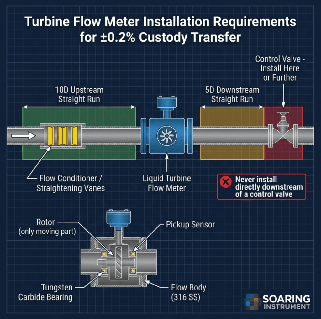
Figure 3: Correct installation layout for custody transfer grade turbine flow meter — 10D upstream straight run is the minimum; flow conditioner recommended for non-ideal piping
Failure to meet straight-run requirements introduces swirl and asymmetric velocity profiles, which can add 0.5%–2.0% systematic error — completely defeating a ±0.2%R calibrated meter.
3. Moving Parts Wear
The turbine rotor bearing is the meter’s Achilles’ heel. It is the only moving part subject to friction and wear. In custody transfer applications:
- Use meters with tungsten carbide bearings for extended service life
- Inspect bearings at each calibration interval
- Monitor K-factor trend — a rising K-factor indicates increasing bearing drag (meter is under-reading actual flow)
4. Fluid Cleanliness
Suspended particles > 50 μm can score bearing surfaces and chip blade edges. For ±0.2%R applications:
- Install upstream Y-strainer or duplex strainer, typically 100–150 mesh
- Monitor differential pressure across the strainer
- For crude oil applications with wax or sediment, consider periodic solvent pigging of the meter run
5. Pulsating Flow
Pulsations from reciprocating pumps or compressors distort the rotor’s angular velocity, making the time-averaged pulse count systematically higher than true flow. Mitigation:
- Install surge suppressor or pulsation damper upstream
- Verify flow with an upstream static pressure measurement
- Use a meter with dual-rotor design for pulsation immunity (where available)
Custody Transfer Flow Meter: Regulatory and Standards Context
In custody transfer applications — particularly for oil, natural gas, and petroleum products — meter selection and operation must comply with recognized standards:
| Medium | Key Standard | Requirements |
|---|---|---|
| Liquid hydrocarbon | API MPMS Chapter 5.3 (Measurement of Liquid Hydrocarbons by Turbine Meters) | Calibration traceability, prover requirements |
| Natural gas | AGA Report No. 7 | K-factor curve, installation specifications |
| General liquid | ISO 5167 | Uncertainty calculation, measurement traceability |
| Legal trade | OIML R 117-1 | Custody transfer approval, MID compliance (EU) |
For liquid custody transfer, Wikipedia confirms that the accepted industry standard requires overall uncertainty of ±0.25% or better for liquid flow measurement — confirming that a properly calibrated ±0.2%R liquid turbine meter meets this threshold.
For gas custody transfer, the ±1.0% standard uncertainty requirement technically allows gas turbine meters into the measurement system — but only when combined with corrective flow computers and frequent calibration.
For more on standards compliance, see: What Are the Essential Flow Meter Accuracy Standards You Need to Know?
Turbine vs. Other Custody Transfer Flow Meter Technologies
When evaluating custody transfer options, engineers often compare turbine meters against alternatives:
| Technology | Typical Accuracy | Moving Parts | Pressure Drop | Best For |
|---|---|---|---|---|
| Liquid turbine (±0.2%R grade) | ±0.2%R | Yes (rotor) | Moderate | Clean liquid, petroleum products |
| Positive displacement | ±0.1%–±0.25% | Yes (multiple) | Higher | Viscous liquids, low flow |
| Coriolis | ±0.1%–±0.5% | No | Higher | Mass flow, high-value chemicals |
| Ultrasonic (multi-path) | ±0.5%–±1.0% | No | Negligible | Large pipes, gas, crude oil |
| Vortex | ±1.0%–±1.5% | No | Moderate | Steam, general gas |
The turbine’s competitive advantage in custody transfer: For clean, low-viscosity liquids (refined petroleum products, chemicals, alcohols) in the DN15–DN200 range, a calibrated ±0.2%R liquid turbine offers the best cost-performance ratio for custody transfer. Its K-factor stability in the viscosity-independent Reynolds number range makes it predictable and auditable.
See also: How Do Turbine and Electromagnetic Flow Meters Compare? and How Do Different Flow Meter Technologies Compare in Performance and Application?
Installation Best Practices for ±0.2% Turbine Flow Meter Performance
From our field commissioning experience across oil & gas and chemical plants, here is the non-negotiable installation checklist:
- Verify fluid cleanliness: Install upstream strainer; check differential pressure before meter commissioning
- Meet straight-run requirements: 10D upstream, 5D downstream; install flow conditioner if piping is non-ideal
- Eliminate vibration sources: Mount meter on vibration-isolated spool; do not install near reciprocating pumps
- Confirm viscosity at operating temperature: Match to calibration conditions; for wide temperature swings, use temperature-compensated K-factor
- Commission with a reference meter: For high-stakes custody installations, run in parallel with a calibrated master meter for 24–72 hours post-commissioning to verify in-situ performance
- Document baseline K-factor curve: Record at commissioning to detect drift at future calibrations
For a complete installation walkthrough: Turbine Flow Meter Installation Guidelines: How to Get It Right?
Troubleshooting: When Your Turbine Flow Meter Loses Accuracy
| Symptom | Probable Cause | Diagnostic Step | Solution |
|---|---|---|---|
| Meter reading consistently high | Bearing wear ↑ mechanical drag | Compare K-factor to baseline curve | Recalibrate; replace bearings |
| Intermittent spikes in flow reading | Pulsation / vibration | Install vibration sensor; check upstream pump condition | Add pulsation damper; isolate meter |
| Low-flow accuracy degraded | Viscosity change or strainer blockage | Measure ΔP across strainer; check fluid temp | Clean strainer; re-verify K-factor at low-flow points |
| Accuracy OK at high flow, poor at low flow | Single K-factor programmed in flow computer | Review flow computer configuration | Input multi-point K-factor calibration curve |
| Meter reads zero at known flow | Rotor seized; debris blocking rotor | Remove and inspect rotor/bearings | Replace rotor assembly; clean internals |
For more troubleshooting: Turbine Flow Meter Troubleshooting: How to Fix Common Issues?
FAQ: Turbine Flow Meter Accuracy and Custody Transfer
Q1: Can a gas turbine flow meter achieve ±0.2% accuracy for natural gas custody transfer?
A: Not with the standard product specification. Our gas turbine flow meters are rated at ±1.0%R to ±1.5%R. For natural gas custody transfer to AGA-7 or ISO 9951 standards, you would need either: (a) a specially factory-calibrated unit with flow-computer K-factor correction, or (b) an alternative technology such as an ultrasonic flowmeter. The repeatability of gas turbines (0.05%–0.2%) is excellent, meaning they could serve as check meters, but not as the primary fiscal meter at ±0.2%.
Q2: How often must a ±0.2%R turbine flow meter be recalibrated for custody transfer?
A: In most custody transfer contracts and applicable standards (API MPMS, AGA-7), recalibration is required at least annually for liquid turbines, and typically before/after high-value batch transfers. For continuous high-volume pipelines, 6-month calibration is the practical industry norm. Any event that introduces potential measurement drift (bearing replacement, strainer cleaning with partial disassembly, significant viscosity changes) requires an immediate recalibration check before resuming commercial metering.
Q3: What is accuracy class 0.2 for a turbine flow meter?
A: Accuracy Class 0.2 means the meter maintains within ±0.2% of the true volumetric flow rate across its specified operating range, under the calibration conditions. It is a high-precision designation, typically reserved for trade measurement, laboratory reference applications, and custody transfer of high-value fluids. Our liquid turbine offers this as a customized specification (as opposed to standard classes 1.0 or 0.5).
Q4: Is ±0.2%R better than ±0.2%FS?
A: Yes, significantly. ±0.2%R (of Reading) means the error is always 0.2% of whatever the actual flow is. ±0.2%FS means the error is 0.2% of the maximum range — which at 10% of full scale represents a 2% error relative to the actual flow. For custody transfer where flows can vary, %R is the correct and more favorable specification.
Q5: What straight-run pipe length is needed for a turbine meter used in custody transfer?
A: Minimum 10 pipe diameters (10D) of straight, undisturbed pipe upstream, and 5D downstream. For custody transfer applications involving flow conditions with upstream bends in multiple planes or partially-open valves, 20D upstream is recommended, or a flow conditioner (vane-type straightener) installed at the 5D upstream point. Never install a turbine meter immediately downstream of a control valve.
Q6: Can a turbine flow meter be used for crude oil custody transfer?
A: Yes, turbine meters are widely used for crude oil custody transfer (API MPMS specs). The key challenge is crude oil’s varying viscosity with temperature and composition. The meter must be calibrated with representative crude at operating conditions, fitted with a multi-point K-factor curve, and used with an online density measurement (densitometer) for mass flow calculation. Regular prover runs are required.
Q7: What is the difference between turbine meter calibration and proving?
A: Calibration establishes the K-factor curve of the meter against a reference standard, typically done at a calibration lab or with a portable master meter. Proving (or in-situ proving) verifies the meter’s current K-factor against a pipe prover or master meter in the field, in-line, at actual operating conditions. Proving is a field verification step; calibration is the foundational accuracy establishment. Custody transfer systems require regular proving — often before, during, and after major batch transfers.
Conclusion: Matching Meter to Application Is the Core Skill
The ±0.2% precision threshold for trade metering is achievable — but only with the right product choice and a disciplined calibration and maintenance program.
Key takeaways:
- ✅ Liquid Turbine Flow Meter (high-precision grade) achieves ±0.2%R — suitable for custody transfer of petroleum products and liquid chemicals
- ❌ Gas Turbine Flow Meter is rated ±1.0%–±1.5%R — excellent for process monitoring, but does not meet typical ±0.2% custody transfer requirements without additional compensation systems
- Calibration must use a multi-point K-factor curve (not a single K value) stored in a flow computer
- Viscosity match between calibration and operating conditions is the single most important variable
- Installation quality — straight runs, cleanliness, vibration isolation — determines whether laboratory accuracy translates to field accuracy
Ready to Specify a Custody Transfer Turbine Flow Meter?
If your application requires ±0.2% precision for trade metering of liquid flows, we can configure a Soaring Liquid Turbine Flow Meter to your exact process conditions: fluid type, viscosity, temperature range (−20°C to +120°C), operating pressure, and output protocol (pulse, 4-20mA, RS485, HART).
📩 Contact our metering engineers for a technical review of your custody transfer application.
🔗 Explore our product pages:
Related Articles
- Turbine Flow Meter Working Principle: How Does It Operate?
- Turbine Flow Meter K-Factor Calculation: Know the Numbers for Precision
- Understanding Turbine Flow Meter Turndown Ratio: Why Is It Critical?
- How Often Do Flow Meters Need To Be Calibrated?
- What Is The Standard For Calibration Of Flowmeter?
- Why Choose Turbine Flow Meters for Industrial Applications?
- How Do Turbine and Electromagnetic Flow Meters Compare?
Published by Shanghai Soaring Instrument Technology Co., Ltd. | soaringinstrument.com
No. 181 Zhongshe Road, Songjiang District, Shanghai, China | [email protected]