In our years of supporting steam measurement systems, the most common question we receive after installation is: "How do I get the flow signal into my DCS?"
Many engineers install a steam flow meter only to realize the raw sensor signal cannot be directly read by their control system. The solution? A steam flow transmitter — a vortex flow meter with integrated electronics that converts the measurement into standardized industrial signals (4-20mA, pulse, HART) for seamless control system integration. These flow measuring devices can accurately measure both saturated steam and superheated steam in industrial applications.
Quick Answer: A steam flow transmitter (also known as a vortex flow transmitter with integrated electronics) outputs standardized signals (4-20mA, pulse, or HART) for direct integration with DCS, PLC, or SCADA systems. For accurate mass flow measurement, choose models with built-in temperature and pressure compensation like the LUGB-Z.
This guide covers output signal types, DCS/PLC integration best practices, and troubleshooting — based on real field experience from hundreds of installations.
📘 Background: For steam flow meter types and selection criteria, see our pillar guide: Steam Flow Meter: Types, Selection & Best Practices
What Is a Steam Flow Transmitter?
The terms "flow meter" and "flow transmitter" are often used interchangeably, but there’s an important distinction:
| Term | Definition | Output |
|---|---|---|
| Flow Meter | The sensing device (primary element) | Raw signal or local display only |
| Flow Transmitter | Sensor + integrated signal conditioning electronics | Standardized industrial signals (4-20mA, HART, RS-485) |
In modern vortex steam flow meters, the sensor and transmitter are typically integrated into a single unit. The body is typically constructed from stainless steel for durability and corrosion resistance. When we refer to a "steam flow transmitter," we’re emphasizing its signal output and remote monitoring capabilities — the features that enable integration with plant control systems.
How Vortex Steam Flow Transmitters Work
Vortex flow meters operate on the principle of the Kármán vortex street (also called the von Kármán effect). When steam flows past a non-streamlined obstruction called a bluff body (or shedder bar), alternating vortices are generated on each side — a phenomenon known as vortex shedding.
The frequency of these vortices is directly proportional to the flow velocity, following the relationship defined by the Strouhal number:
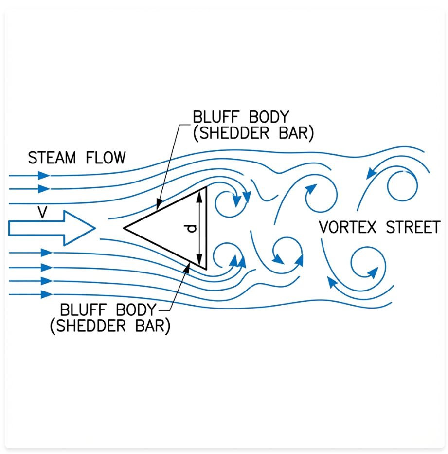
f = St × V / dWhere:
- f = vortex shedding frequency (Hz)
- St = Strouhal number (dimensionless, typically ~0.2)
- V = flow velocity (m/s)
- d = bluff body width (m)
A piezoelectric sensor embedded behind the bluff body detects the pressure fluctuations caused by the alternating vortices and converts them into an electrical signal. This signal is then processed by the transmitter electronics to calculate flow rate and output standardized signals (4-20mA, pulse, or digital). Because vortex flow meters have no moving parts, they offer exceptional reliability and require minimal maintenance compared to turbine-type meters.
Output Signal Types for Steam Flow Transmitters
Choosing the right output signal depends on your control system requirements and installation constraints. Here’s what we recommend based on our field experience:
1. 4-20mA Analog Output
The 4-20mA current loop is the industry standard for process control and the most common steam meter output signal. It’s reliable, well-understood, and compatible with virtually every DCS and PLC on the market.
How It Works:
- 4 mA = Zero flow (live zero allows detection of wire breaks)
- 20 mA = Full-scale flow
- Linear relationship between current and flow rate
Advantages:
- ✅ Universal compatibility with all DCS/PLC systems
- ✅ Two-wire design saves installation cost
- ✅ Long transmission distance (up to 1000m without signal degradation)
- ✅ Immune to electrical noise (current signal, not voltage)
Soaring Instrument Specifications:
- Output: 4-20mA two-wire current output
- Power Supply: 12-24V DC or 3.6V lithium battery (self-powered)
- Max Transmission Distance: ≤1000m
2. Pulse/Frequency Output
Pulse output is ideal for totalization — when you need to count the total volume or mass of steam consumed over time.
How It Works:
- Each pulse represents a fixed quantity (e.g., 1 pulse = 0.01 m³ or 1 kg)
- Pulse frequency is proportional to instantaneous flow rate
Advantages:
- ✅ Perfect for cumulative measurement (totalizer)
- ✅ High resolution
- ✅ Direct connection to PLC high-speed counter inputs
Typical Parameters:
- Pulse type: Square wave or open-collector
- Maximum frequency: 1-10 kHz (application dependent)
3. RS-485 / HART Digital Communication
Digital communication protocols enable two-way data exchange — not just reading flow values, but also remote configuration and diagnostics. Unlike differential pressure transmitters that require impulse lines, vortex transmitters with digital output offer simpler installation.
RS-485 (Modbus RTU):
- Multi-drop network capability (up to 32 devices on one bus)
- Useful for connecting multiple transmitters to a single SCADA system
HART Protocol:
- Digital signal superimposed on the 4-20mA analog signal
- Provides bidirectional communication without additional wiring
- Enables remote parameter configuration, diagnostics, and multi-variable output
Soaring Instrument LUGB-Z Capabilities:
- Communication: RS-485 Modbus RTU, HART protocol (optional)
- Supports remote configuration via HART communicator or SCADA
For detailed HART protocol specifications, see the official FieldComm Group (HART Foundation) documentation.
RS-485 Modbus RTU Configuration
| Parameter | Default Value |
|---|---|
| Baud Rate | 9600 bps |
| Data Bits | 8 |
| Parity | None |
| Stop Bits | 1 |
| Device Address | 1 (configurable 1-247) |
| Protocol | Modbus RTU |
For Modbus protocol details and register mapping standards, refer to Modbus.org.
2-Wire vs 4-Wire Power Supply
Understanding power supply options is essential for correct installation:
| Type | Description | Use Case |
|---|---|---|
| 2-Wire (Loop Powered) | Power and 4-20mA signal share the same cable pair | Simple installation, most common, lower cost |
| 4-Wire (External Powered) | Separate power supply; transmitter can output multiple signals simultaneously | High-power transmitters, dual output (4-20mA + pulse) |
| Battery Powered | Self-contained 3.6V lithium battery | Remote locations without power supply |
Soaring Instrument LUGB-Z/LUGB-X: Supports both 2-wire loop powered (12-24V DC) and 3.6V lithium battery (self-powered, typically 2+ years battery life).
Note for Hazardous Areas: In Ex-rated zones (Zone 1/2), you may need to use intrinsic safety barriers (Ex ia) or galvanic isolators in addition to explosion-proof transmitters. Consult your plant safety engineer for proper configuration.
DCS/PLC Integration: Best Practices
Integrating a steam flow transmitter with your control system requires careful planning. Here’s a systematic approach based on our project experience:
Signal Type Selection Guide
| Application Scenario | Recommended Signal | Reason |
|---|---|---|
| Basic process monitoring | 4-20mA | Simple, reliable, universal compatibility |
| Energy metering / totalization | Pulse | Accurate cumulative measurement |
| Remote diagnostics & configuration | HART over 4-20mA | Bidirectional communication, no extra wiring |
| Multi-device network | RS-485 Modbus | Low-cost networking of multiple instruments |
Compatibility with Popular Control Systems
Our steam flow transmitters have been successfully integrated with:
- Siemens S7-300/400, S7-1500 (via SM 331 AI module)
- Allen-Bradley ControlLogix (via 1756-IF8 AI module)
- Emerson DeltaV (via AI CHARM)
- Honeywell Experion (via AI LLMUX)
- ABB 800xA (via AI810)
The 4-20mA interface is universally compatible. For HART integration, ensure your AI module supports HART pass-through.
Typical 4-20mA Two-Wire Wiring
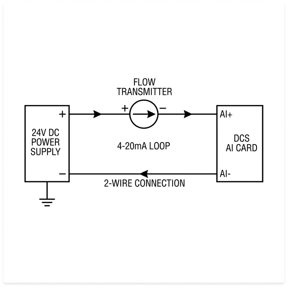
Important Notes:
- Observe polarity — incorrect polarity can damage the transmitter
- Use shielded twisted-pair cable for noise immunity
- Ground the cable shield at the DCS end only (single-point grounding)
HART Communication Over 4-20mA
HART (Highway Addressable Remote Transducer) protocol allows digital communication without additional wiring by superimposing a digital signal on the analog 4-20mA loop.
Setup:
- Connect the HART modem in parallel with the 4-20mA loop
- Verify device polling address (default is usually 0 or 1)
- Use HART communicator software to read/write parameters
Span Configuration
Critical: The 4-20mA output range must be correctly mapped in your DCS.
Example Configuration:
- Transmitter range: 0-1000 kg/h
- 4 mA = 0 kg/h
- 20 mA = 1000 kg/h
- Configure DCS AI module with matching engineering units
Field Tip: We’ve seen cases where the DCS showed incorrect readings simply because the AI module was configured for 0-100% instead of the actual flow range.
Lessons from the Field: Real Integration Challenges
Case 1: Why Grounding Matters
A chemical plant contacted us after their new steam flow transmitter showed erratic 4-20mA readings — the signal would randomly spike even with stable flow.
Root Cause: After site inspection, we discovered the transmitter was not properly grounded. The stainless steel pipe had a coating that broke the electrical ground path.
Solution: We installed a dedicated grounding strap from the transmitter body to the plant grounding grid.
Result: Signal stability improved immediately. The lesson? Never assume the pipe provides adequate grounding.
Case 2: HART Communication Failure
An oil refinery integrator spent two days troubleshooting why their HART communicator couldn’t detect the transmitter.
Root Cause: During factory configuration, the device address had been changed from the default (0) to address 15 — but the integrator was polling address 0.
Solution: A simple address scan identified the correct device address.
Lesson: Always verify the HART polling address before assuming hardware failure.
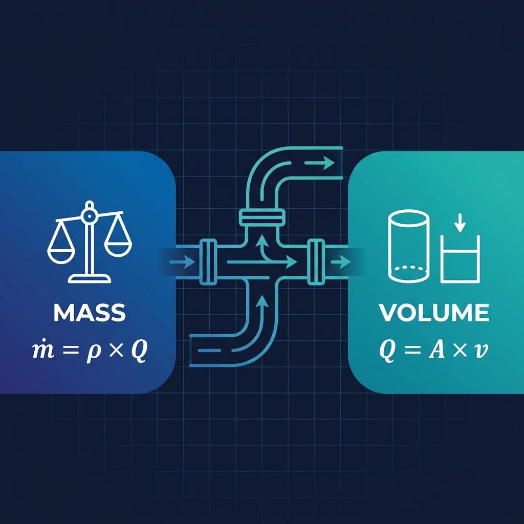
Temperature & Pressure Compensation in Steam Flow Transmitters
Steam is a compressible fluid — its density changes dramatically with temperature and pressure. Without real-time compensation, volumetric flow cannot be accurately converted to mass flow.
Why Compensation Is Essential
| Steam Type | Compensation Required | Method |
|---|---|---|
| Saturated Steam | Pressure only | Pressure sensor + steam table lookup |
| Superheated Steam | Temperature + Pressure | T&P sensors + steam table lookup |
LUGB-Z Integrated Compensation
The Soaring Instrument LUGB-Z Temperature & Pressure Compensation Type vortex transmitter includes:
- Built-in PT1000 temperature sensor
- Built-in pressure sensor
- Microprocessor with IAPWS-IF97 steam table lookup
- Direct mass flow output (kg/h) — no external flow computer needed
Advantages:
- ✅ Eliminates need for external transmitters and flow computers
- ✅ Reduces installation complexity and cost
- ✅ Improves system reliability (fewer components = fewer failure points)
Technical Specifications: LUGB-Z vs LUGB-X
| Parameter | LUGB-Z (T&P Compensation) | LUGB-X (LCD Type) |
|---|---|---|
| Display | Dual-row LCD, 8-digit | Dual-row LCD, 8-digit |
| Output Signal | 4-20mA two-wire | 4-20mA two-wire |
| Communication | RS-485, HART (optional) | RS-485 (optional) |
| Temperature Compensation | ✅ Built-in PT1000 | ✅ Online compensation |
| Pressure Compensation | ✅ Built-in pressure sensor | ❌ Requires external sensor |
| Density Compensation | Online + fixed value | Fixed value only |
| Mass Flow Output | ✅ Direct kg/h output | ❌ Requires external calculation |
| Power Supply | 12-24V DC / 3.6V lithium | 12-24V DC / 3.6V lithium |
| Small Signal Cut-off | ✅ User-configurable | ✅ User-configurable |
| Explosion-Proof | Exd II CT6 Gb (optional) | Exd II CT6 Gb (optional) |
Additional Specifications (from Product Catalog):
| Parameter | Value |
|---|---|
| Medium Temperature | -40°C to +250°C (optional +350°C) |
| Medium Pressure | 1.6 MPa, 2.5 MPa, 4.0 MPa (customizable) |
| Accuracy | ±1.0%, ±1.5% |
| Turndown Ratio | 10:1 |
| Velocity Range (Steam) | 5.0 – 70 m/s |
| Body Material | Stainless steel (1Cr18Ni9Ti) |
| Protection Class | IP65 |
| Insertion Type Accuracy | ±1.5%, ±2.5% |
Pipe Diameter Range:
- Inline type: DN15-DN300
- Insertion type: DN80-DN2000 (for large pipes, hot-tap installation)
Troubleshooting Common Integration Issues
Based on our technical support experience, here are the most common problems and solutions:
| Symptom | Probable Cause | Solution |
|---|---|---|
| 4-20mA stuck at 4 mA | No flow / velocity below minimum | Verify actual flow; check for blockage |
| Signal fluctuates wildly | Wet steam / poor grounding / vibration | Install steam separator; check grounding strap; isolate from vibration |
| HART communication fails | Wrong polling address / baud mismatch | Verify address (scan if needed); check cable polarity |
| RS-485 no response | Incorrect Modbus config / termination | Confirm baud rate (9600), parity (None); check termination resistor |
| DCS shows wrong reading | Span misconfiguration | Re-verify: 4mA = zero, 20mA = full scale |
| Transmitter powers up but no display | Low battery / power supply issue | Check battery voltage (≥2.0V); verify 24V DC supply |
Common Mistakes We See
- Ignoring grounding requirements — coated pipes break the ground path
- Using unshielded cable for 4-20mA — leads to noise pickup
- Mismatched HART address — default vs. factory-configured
- Incorrect flow direction — some meters are unidirectional (check arrow)
Related: For more flow meter troubleshooting tips, see Why Is My Flow Meter Not Reading Correctly? A Complete Troubleshooting Guide.
How to Select the Right Steam Flow Transmitter
Selection Decision Flow
What do you need?
│
├── Mass flow output (kg/h) required?
│   ├── Yes → LUGB-Z (T&P compensation)
│   └── No → LUGB-X or basic + external flow computer
│
├── Remote diagnostics / configuration?
│   ├── Yes → Choose HART or RS-485 option
│   └── No → 4-20mA is sufficient
│
├── Large pipe diameter (DN200+)?
│   └── Yes → Insertion-type vortex transmitter
│
├── Can you provide 24V DC power?
│   ├── Yes → Loop-powered (2-wire)
│   └── No → 3.6V lithium battery type
│
└── Hazardous area (Ex zone)?
    └── Yes → Specify Exd II CT6 Gb explosion-proof version
Common Applications
Power Generation
- Boiler steam output monitoring
- Turbine inlet flow measurement
- Energy efficiency auditing
Success Story: A 50 MW power plant integrated our LUGB-Z transmitters with their Siemens PCS7 DCS. By using 4-20mA + HART, they achieved both real-time flow monitoring and remote diagnostics — reducing annual calibration downtime by 40%.
Chemical & Petrochemical
- Process heating steam measurement
- Reactor steam control
- Steam cracking operations
Food & Beverage
- Sterilization steam monitoring (FDA compliance)
- CIP (Clean-in-Place) steam metering
HVAC & District Heating
- Building heating steam metering
- Energy cost allocation for tenants
Frequently Asked Questions (FAQ)
What is the difference between a flow meter and a flow transmitter?
A flow meter is the sensing device that detects flow. A flow transmitter integrates the sensor with electronics that convert the measurement into standardized industrial signals (4-20mA, pulse, HART) for control system integration.
What output signal is best for steam flow measurement?
4-20mA is the most universal choice for process control. Use pulse output for totalization (cumulative measurement). Use HART if you need remote diagnostics and configuration without extra wiring.
Can I measure mass flow directly with a steam flow transmitter?
Yes, if you choose a model with integrated temperature and pressure compensation (like the LUGB-Z). Otherwise, you need an external flow computer to convert volumetric flow to mass flow.
Can I power the transmitter directly from a PLC 24V output?
Yes, as long as the PLC output can supply sufficient current (typically 20-30 mA at 24V DC). Most 2-wire loop-powered transmitters work well with PLC 24V outputs. Check the transmitter’s current consumption specifications.
What type of cable should I use for 4-20mA signal transmission?
Use shielded twisted-pair cable (e.g., Belden 9501 or equivalent). Ground the shield at the DCS/PLC end only to prevent ground loops. For distances over 300m, consider using heavier gauge wire (AWG 16-18) to minimize voltage drop.
Conclusion
Key Takeaways:
A steam flow transmitter is a vortex flow meter with integrated signal conditioning for control system integration.
Choose 4-20mA for simple and reliable process control, pulse for totalization, and HART/RS-485 for remote diagnostics and configuration.
For accurate mass flow measurement of steam, select a model with integrated T&P compensation (Soaring Instrument LUGB-Z) to eliminate the need for external flow computers.
Proper grounding and correct span configuration are the two most common issues in DCS integration — don’t overlook them.
When in doubt, use shielded cable and verify the HART address before troubleshooting further.
Get Expert Integration Support
Our engineering team has supported hundreds of steam flow transmitter integrations across power plants, chemical facilities, and food processing plants. We can help with:
- Signal type selection
- DCS/PLC configuration guidance
- Troubleshooting support
- On-site commissioning assistance
Request Free Integration Consultation | View Vortex Flow Transmitter Specifications