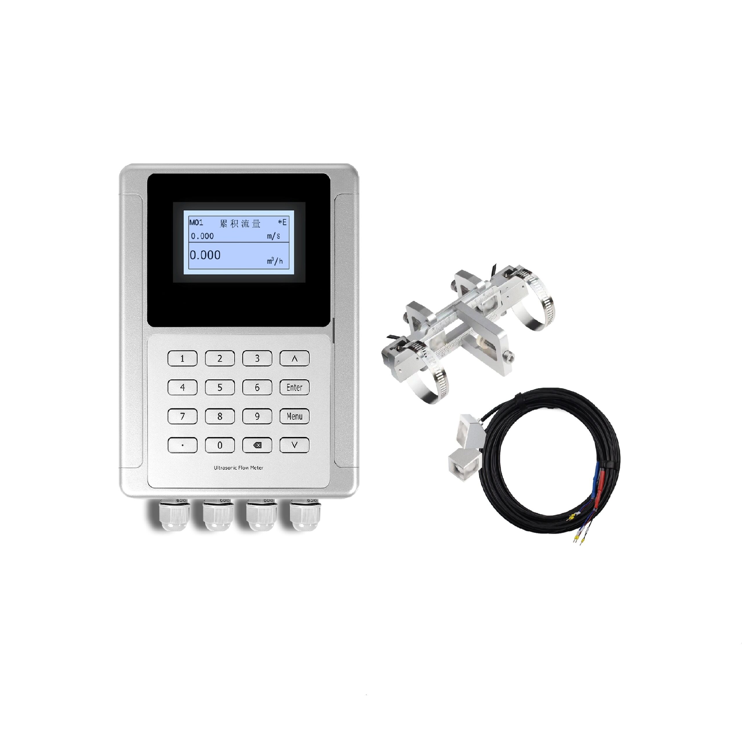
Wall-Mounted Ultrasonic Flow Meter
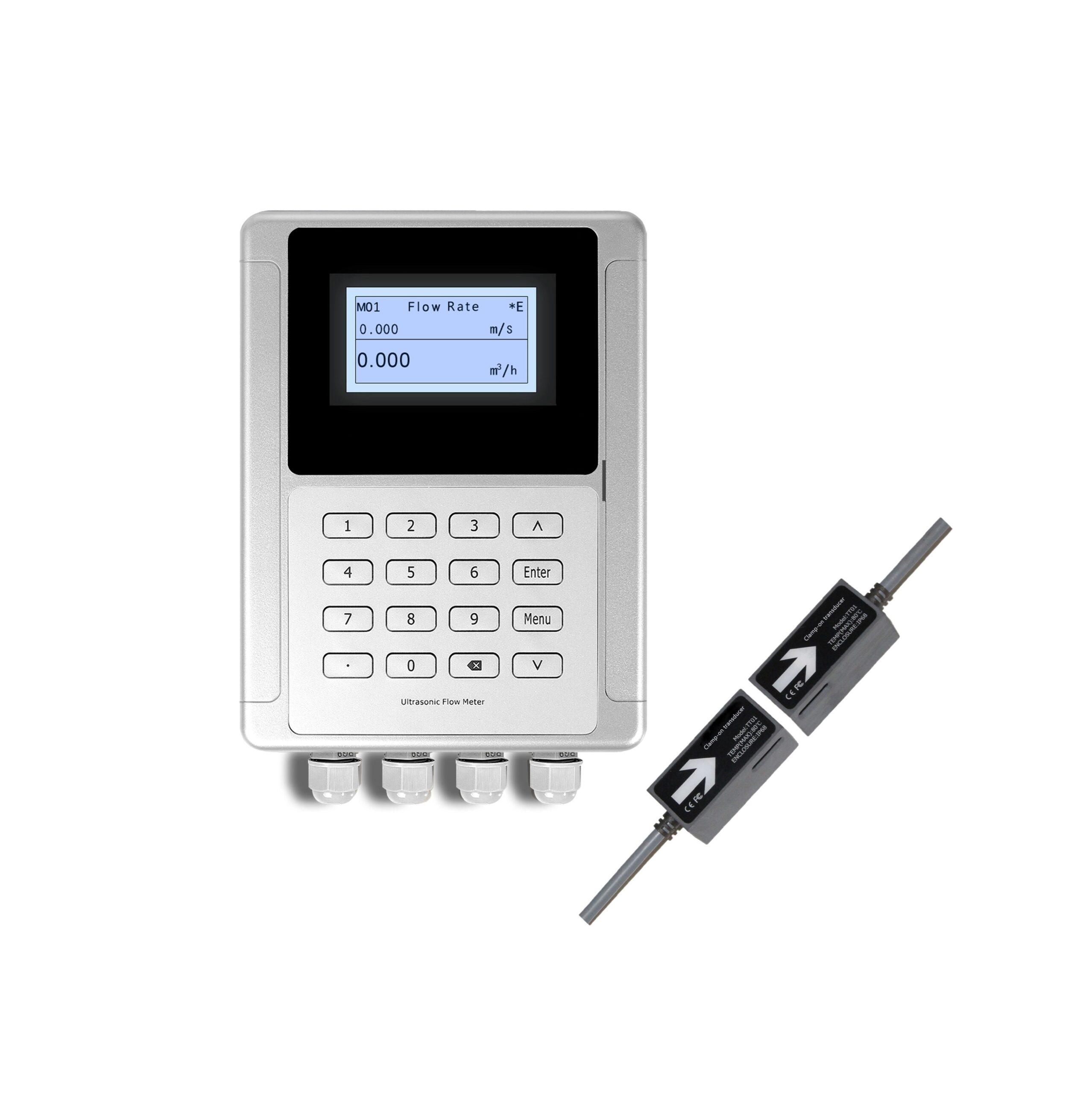
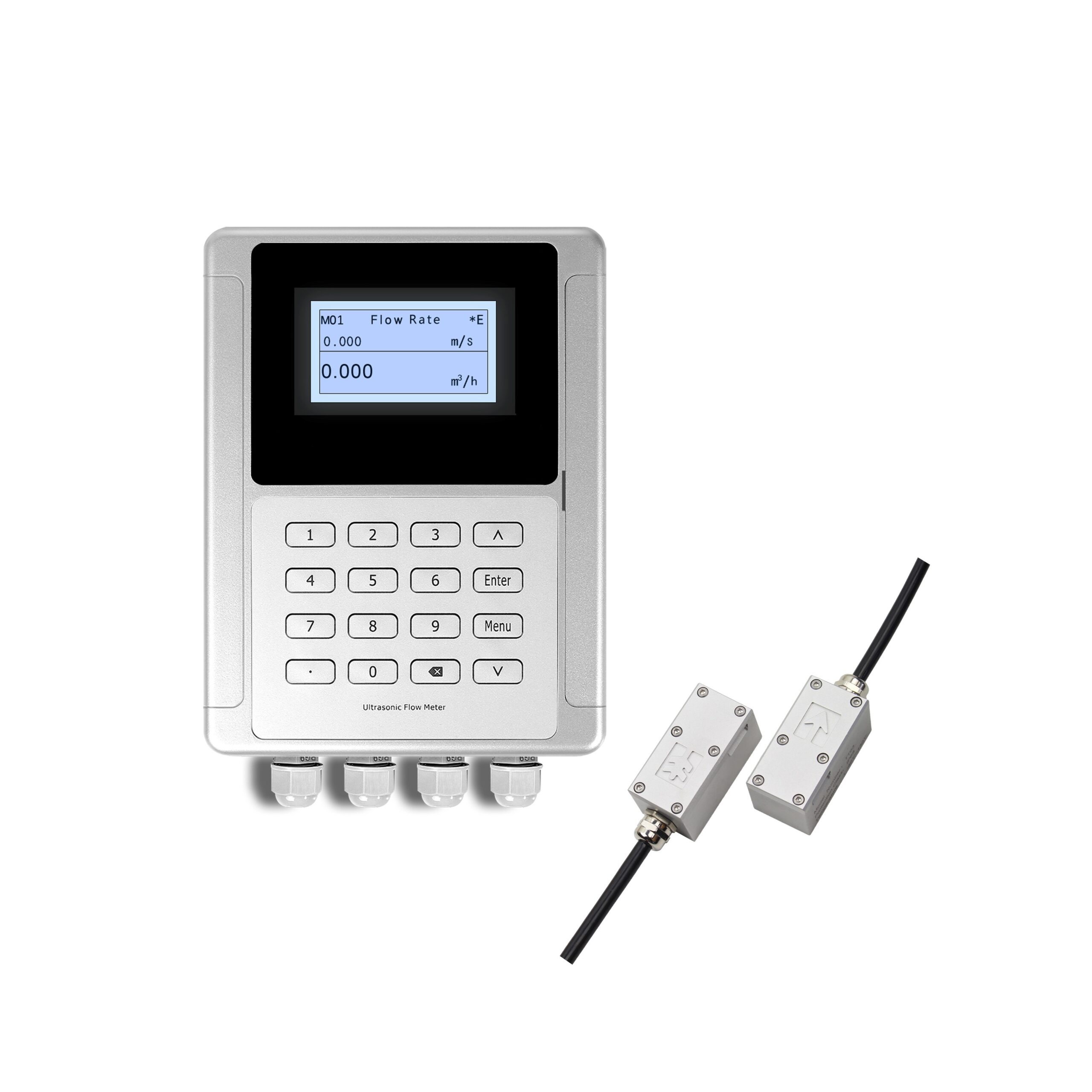
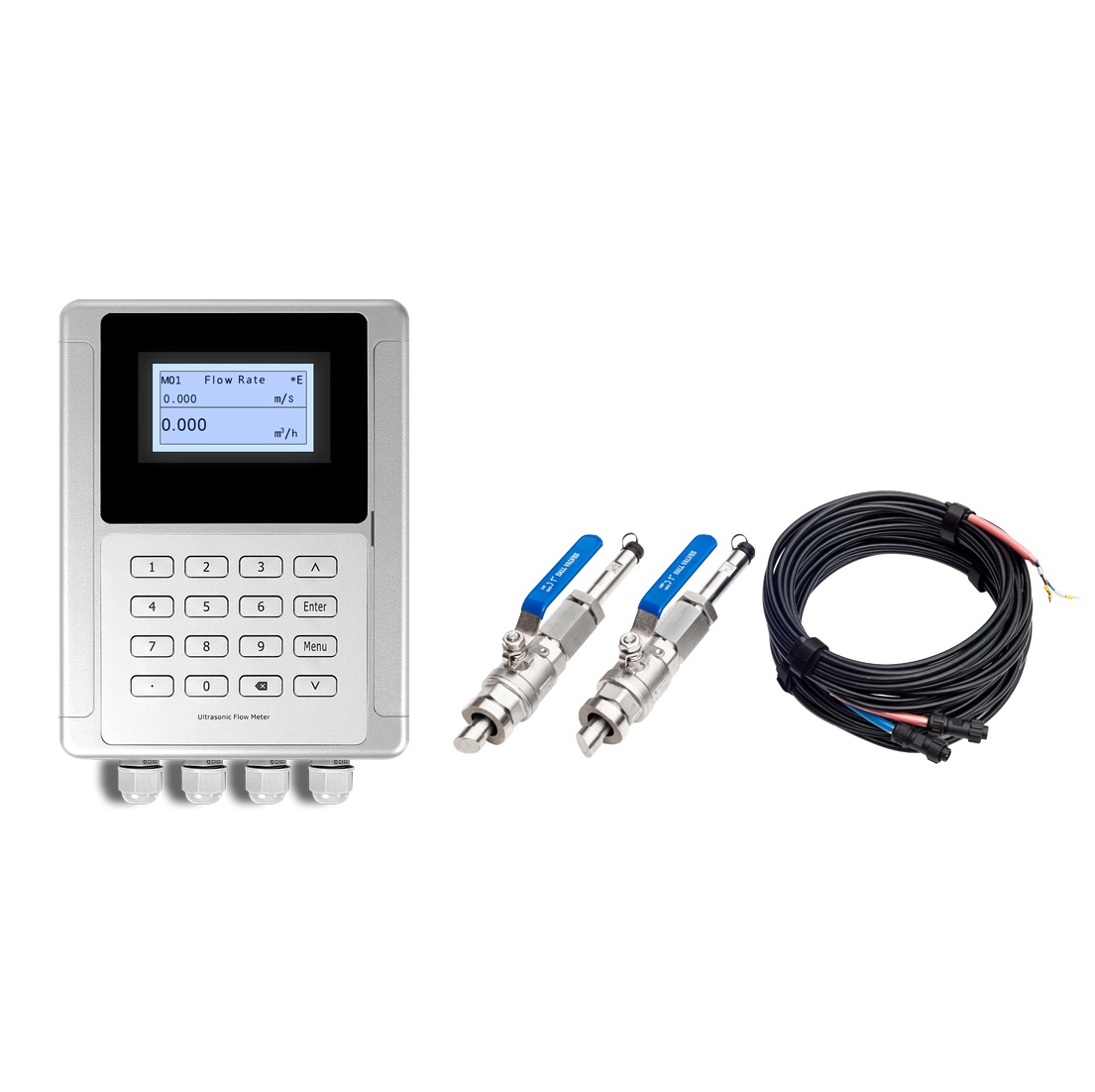
Wall-Mounted Ultrasonic Flow Meter
✓ IP68 Transducers · ✓ IP65 Transmitter · ✓ CE Compliant
Pipe Size: DN15 – DN1200 (½″ – 48″)
Medium Temp: -40°C to +180°C
Flow Velocity: ±0.03 m/s to ±12 m/s
Measurement: Bi-directional
Output: 4–20 mA | RS485 Modbus | Pulse
Installation: No Cutting Pipes
Lead Time: 7 days · MOQ: 1 Unit
Engineer replies within 24 hours · Free technical consultation
Technical Specifications
Performance
| Parameter | Specification |
|---|---|
| Measurement Principle | Transit-time difference (TGA technology) |
| Flow Velocity Range | ±0.03 m/s to ±12 m/s (±0.09 ft/s to ±39 ft/s) |
| Accuracy | ±1% of measured value |
| Repeatability | 0.2% of measured value |
| Linearity | ±1% |
| Pipe Size Range | DN15–DN1200 (½″–48″) |
| Bi-directional Measurement | Yes — forward, reverse, and net flow totalization |
| Measuring Rate | >300 measurements per second |
| Bubble/Impurity Tolerance | Continuous bubbles or impurities up to 5 seconds |
Transmitter (Wall-Mounted Unit)
| Parameter | Specification |
|---|---|
| Display | 240×128 backlit LCD, 4-line display |
| Analog Output | 4-20mA, max load 750Ω |
| Pulse Output | 0–10 KHz |
| Communication | RS232/RS485 Modbus (M-BUS or HART optional) |
| Power Supply | DC 10–36V / AC 90–245V |
| Housing Material | PC+ABS |
| Protection Rating | IP65 |
| Operating Temperature | -20°C to +60°C |
| Humidity | Up to 99% RH, non-condensing |
Transducer
| Parameter | Specification |
|---|---|
| Operating Temperature |
TT01 / TT02: -40°C to +80°C (DN25–DN1200) TT03 / TT05: -40°C to +130°C (DN25–DN1200) TT02H: -20°C to +180°C (DN25–DN1200) TT02S: 0°C to +65°C (DN15–DN40) TT03S: 0°C to +115°C (DN15–DN40) |
| Protection Rating | IP68 (fully submersible) |
| Construction | Encapsulated design with double-shielded cable |
| Cable Length | Standard: 30 ft (9m) / Maximum: 1000 ft (300m) |
| Transducer Matching | ≤2 nanoseconds between each pair |
Optional: Energy Meter Function
Add the RTD module and PT1000 temperature sensors to configure this meter as a BTU energy meter. Enables measurement of heat and cold consumption in:
- Central heating pipelines
- Air-conditioning refrigeration systems
- District energy networks
Why Engineers Choose Insertion Over Clamp-On for Large Pipes
Insertion transducers consistently outperform clamp-on sensors in three specific situations:
- Thick-walled or lined pipes — Clamp-on sensors must transmit signals through the pipe wall. Insertion probes bypass the wall entirely. They sit directly in the fluid — signal quality is not affected by wall thickness or lining material.
- Long-term permanent installations — Clamp-on sensors need coupling gel between the sensor and pipe. Over time, that gel dries out and signal quality drops. Insertion probes touch the fluid directly — no gel needed, no signal drift. See: How Accurate Are Ultrasonic Flow Meters?
- High-temperature lines (up to 180°C) — The TT05 insertion probe operates at -40°C to +180°C with direct fluid contact, providing reliable signal quality in high-temperature applications.
The trade-off: insertion installation requires a hot tap into the pipe wall. For permanent metering points — especially DN200 and above — the signal quality and long-term stability are worth it.
Not sure which type fits your application? Read our comparison: Inline vs Clamp-On vs Insertion Ultrasonic Flow Meters
Typical Applications
🔧 Municipal Water Distribution — Large Diameter Mains
The Problem: On DN400+ ductile iron or cement mains, clamp-on sensors must transmit signals through a thick pipe wall. Signal quality degrades — especially on lined or composite pipes.
Why Insertion Works Better: The TT05 probe sits directly inside the pipe, bypassing the wall entirely. Signal quality stays consistent regardless of wall thickness or pipe material.
Key Advantage: Hot-tap installation. The meter is installed while the pipeline stays in full operation — no service interruption, no water loss.
Client name available upon NDA — contact us to discuss your project.
🔧 HVAC Chilled Water Loops — Energy Monitoring
The Problem: Mechanical flow meters in chilled water systems cause pressure drop and need regular maintenance. Both add cost to building operations.
Why Insertion Works Better: No moving parts — zero pressure drop and zero scheduled maintenance. Add the optional RTD module and PT1000 temperature sensors to turn it into a full BTU energy meter.
Best For: Building energy management systems, district cooling, central HVAC monitoring.
Can We Meet Your Requirements?
| Requirement | Capability | Status |
|---|---|---|
| Pipe Size DN25–DN300 | Standard configuration | ✅ In stock |
| Pipe Size DN300–DN1200 | Extended insertion probe | ✅ Available ( 7 days lead time) |
| Pipe Size > DN1200 | Custom probe length required | ⚠️ Contact engineering team |
| Clean water / Cooling water | Standard application | ✅ Standard |
| Wastewater (low solids) | Compatible with transit-time method | ✅ Available |
| Chemical fluids | Confirm acoustic compatibility | ⚠️ Requires review |
| Slurries / High-solids fluids | Not suitable for transit-time | ❌ Not recommended |
| Gas / Steam | Liquid measurement only | ❌ Not suitable |
| Accuracy ±1% | Standard specification | ✅ Standard |
| Energy metering (BTU) | Optional RTD module + PT1000 | ✅ Available |
| SCADA/PLC integration | 4-20mA, RS485 Modbus, HART optional | ✅ Available |
Our Capabilities & Boundaries
WHAT WE DO:
- Insertion-type liquid flow measurement using TGA transit-time technology
- Hot-tap installation — meter installed without pipeline shutdown
- Custom transducer cable lengths up to 1000 ft (300m) for remote transmitter locations
- SCADA/PLC integration via 4-20mA, RS485 Modbus, or optional HART/M-BUS
- Optional energy meter function with PT1000 sensors for heating/cooling BTU measurement
WHAT WE DON’T DO:
- Gas or steam flow → Use our vortex flow meter for steam, or thermal mass flow meter for gas
- Slurries or high-solids fluids → Signal scatter makes transit-time unreliable; use our electromagnetic flow meter instead
- Custody transfer at ±0.2% accuracy → This requires Coriolis technology
How It Works
Two probes are inserted into the pipe, facing each other at an angle.
- Probe A sends an ultrasonic pulse with the flow
- Probe B sends a pulse against the flow
Flow makes the downstream pulse arrive faster. The meter measures that time difference and calculates flow velocity. This is the TGA transit-time method — read more: How Does a Transit-Time Ultrasonic Flow Meter Work?
No moving parts. Nothing in the flow path. Nothing to wear out.
Probe Mounting Options
The right method depends on your pipe size and material:
| Method | How the Signal Travels | Best For | Typical Pipe Size |
|---|---|---|---|
| V-Method | Both probes on same side; signal crosses diagonally | Standard choice for most installations | DN80–DN500 |
| Z-Method | Probes on opposite sides; signal crosses directly | Large pipes or fluids with high acoustic damping | DN500+ |
Our engineering team specifies the correct method for your pipe size and material — no guesswork needed on your side.
Ideal Applications
✅ Recommended
| Application | Why Insertion Type Excels |
|---|---|
| Municipal water supply & distribution | Hot-tap install avoids service interruption; no pressure drop |
| Industrial cooling water circuits | Long-term stability; wide flow range covers variable loads |
| HVAC energy metering | Optional BTU function; zero pressure drop |
| Wastewater treatment (low solids) | Transit-time works in fluids with minimal suspended solids |
| Fire protection water systems | No obstruction to emergency water delivery |
| Large-diameter pipeline retrofits (DN200+) | Hot-tap eliminates costly pipe cutting and welding |
❌ Not Recommended For
| Application | Why | Better Alternative |
|---|---|---|
| Slurries or high-solids fluids | Suspended particles scatter ultrasonic signal | Electromagnetic flow meter |
| Gas or steam | Transit-time requires liquid medium | Vortex flow meter (steam) / Thermal mass meter (gas) |
| Non-full pipe conditions | Requires fully filled pipe | Open channel flow meter |
| Pipes with heavy internal scaling | Scaling on transducer faces degrades signal | Clamp-on ultrasonic meter |
Ordering Information
| Item | Details |
|---|---|
| MOQ | 1 unit |
| Standard Lead Time | 7 days |
| Rush Order | Available — contact sales for expedited delivery |
| Payment Terms | T/T |
| Warranty | 12 months from shipment date |
| Packaging | Individual carton with foam protection, ISPM 15 compliant |
| Included Documentation | Factory calibration certificate, operation manual, test report |
Frequently Asked Questions
What is the difference between insertion and clamp-on ultrasonic flow meters?
Clamp-on transducers mount on the outside of the pipe wall — they never touch the fluid. Insertion transducers are mounted through the pipe wall via a hot tap, making direct contact with the liquid. Insertion types offer better long-term signal stability (especially on thick-walled or lined pipes), while clamp-on types offer completely non-invasive installation. See: Inline vs Clamp-On Ultrasonic Flow Meters.
Can this meter be installed without shutting down the pipeline?
Yes. Our insertion transducers support hot-tap installation — the transducer is installed through a valve assembly while the pipeline remains in full operation. No shutdown, no water loss. See: How to Install an Insertion Type Flow Meter.
What pipe materials are compatible?
Because the probe bypasses the pipe wall and sits directly in the fluid, pipe material has minimal impact on measurement quality. Compatible with carbon steel, stainless steel, ductile iron, PVC, concrete-lined, and cement pipes. Have an unusual pipe material? Send us the specs and we’ll confirm compatibility.
What are the straight pipe run requirements?
We recommend 10× pipe diameters upstream and 5× downstream of straight, unobstructed pipe. On a DN200 (8″) pipe, that’s 2 meters upstream and 1 meter downstream. Read more: Critical Straight Run Requirements for Flow Meters.
Can this meter measure flow in both directions?
Yes. Bi-directional measurement across the full range of 0 to ±12 m/s. Built-in totalizers for positive flow, negative flow, and net flow — ideal for HVAC loops and leak detection on distribution mains.
What maintenance does this meter require?
Minimal. No moving parts — no bearings, rotors, or seals to replace. The main task is periodic inspection of the transducer faces for scaling or buildup, typically during scheduled plant shutdowns. The hot-tap valve assembly lets you retract the transducer for inspection without draining the pipe.
What does “wall-mounted” mean — isn’t this an insertion meter?
These describe two different parts of the same system. “Wall-mounted” refers to the transmitter (the electronics/display box), which mounts on a nearby wall or panel. “Insertion” refers to the transducer (the sensor), which is inserted through the pipe wall. Our product combines a wall-mounted transmitter with insertion-type transducers.
Get Your Custom Quote in 24 Hours
At Soaring Instrument, we manufacture both clamp-on and insertion ultrasonic flow meters in-house. We’ll recommend the right configuration for your application — not just the product we happen to sell.
Tell us your pipe size, medium type, and application. Our engineering team responds with a technical recommendation and pricing within 24 hours.
- 📧 [email protected]
- 📞 0086-13585991410
- 🌐 Contact Us Online
What Happens After You Submit?
- Step 1: Engineer reviews and replies within 24 hours
- Step 2: Free 30-minute technical consultation (no obligation)
- Step 3: Detailed proposal with pricing in 3 business days
Related Resources
- What is an Insertion Type Ultrasonic Flow Meter: A Complete Guide
- How to Install an Insertion Type Flow Meter?
- Wall Mount Ultrasonic Flow Meter: Built to Last with Metal & Color TFT
- How Does a Transit-Time Ultrasonic Flow Meter Work?
- How to Choose Ultrasonic Flow Meters for Large Diameter Pipes?
- What Fluids Can Ultrasonic Flow Meters Measure?
- How to Troubleshoot Ultrasonic Flow Meter Signal Loss?
- The Complete Guide of Ultrasonic Flow Meter