A chemical plant engineer once called us about a tuning fork level switch that failed within two weeks of installation. The fork tines were caked in resin, the output signal was erratic, and the production line had already suffered three false shutdowns. The problem? The switch was installed horizontally in a vessel containing viscous epoxy resin—a textbook case of wrong orientation in a challenging application.
We’ve seen this scenario repeat across hundreds of installations. Standard tuning fork level switch installation guides work perfectly for clean water in an open tank. But real industrial processes rarely involve clean water in an open tank.
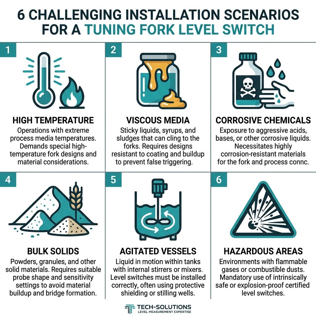
Quick Answer: Tuning fork level switches in challenging applications require scenario-specific installation—vertical orientation for viscous media, process extensions for high-temperature vessels, PTFE-coated forks for corrosive chemicals, and angled mounting away from fill streams for bulk solids. Each challenging scenario demands its own solution.
If you need a refresher on the fundamentals, see our guide on what’s the best way to install a tuning fork level switch. This article goes beyond the basics—focusing on 6 real-world scenarios where standard installation methods fail.

How a Tuning Fork Level Switch Works: Why It Matters for Challenging Installations
Before diving into specific scenarios, understanding the working principle is critical—because every challenging installation problem traces back to one core mechanism.
A vibrating fork level switch uses a piezoelectric crystal to drive two tines at their natural resonant frequency. The resonant frequency is governed by the equation:
f₀ = (1/2π) × √(k/m)
Where f₀ is the natural frequency, k is the fork stiffness, and m is the effective mass. When material contacts the fork, the added mass dampens the vibration—lowering f₀ significantly. The electronics detect this frequency shift and trigger a switching output.
Why this matters for tough applications: Any factor that changes k (temperature-induced material softening) or artificially adds m (sticky buildup on tines) will interfere with accurate detection. External mechanical vibration can inject noise that masks the genuine frequency shift. Understanding this equation helps you anticipate exactly which installation scenarios will create problems—and why the solutions in this guide work.
Soaring Instrument Tuning Fork Level Switch: Key Specifications
| Parameter | Specification |
|---|---|
| Suitable Media | Liquid, granular, and thick substances |
| Fork Structure | All-metal construction, sturdy and durable |
| Key Feature | Large vibration amplitude—shakes off low-viscosity hanging materials |
| Calibration | Automatic learning function for different medium densities |
| Power Input | Wide range for broad application |
| Process Connection | Thread, flange, clamp mounting |
Source: Soaring Instrument Product Catalog
Scenario 1: High-Temperature Process Vessels (Up to 200°C)
Typical applications: Chemical reactors, distillation columns, asphalt storage tanks, steam condensate systems.
The Challenge
Standard tuning fork electronics are rated for ambient temperatures around 60°C. Inside a 180°C reactor, heat conducts through the process connection directly into the electronics housing. We’ve seen cases where the piezoelectric element drifts out of its calibrated frequency range, causing the switch to “lock” in one state—either permanently indicating full or permanently indicating empty.
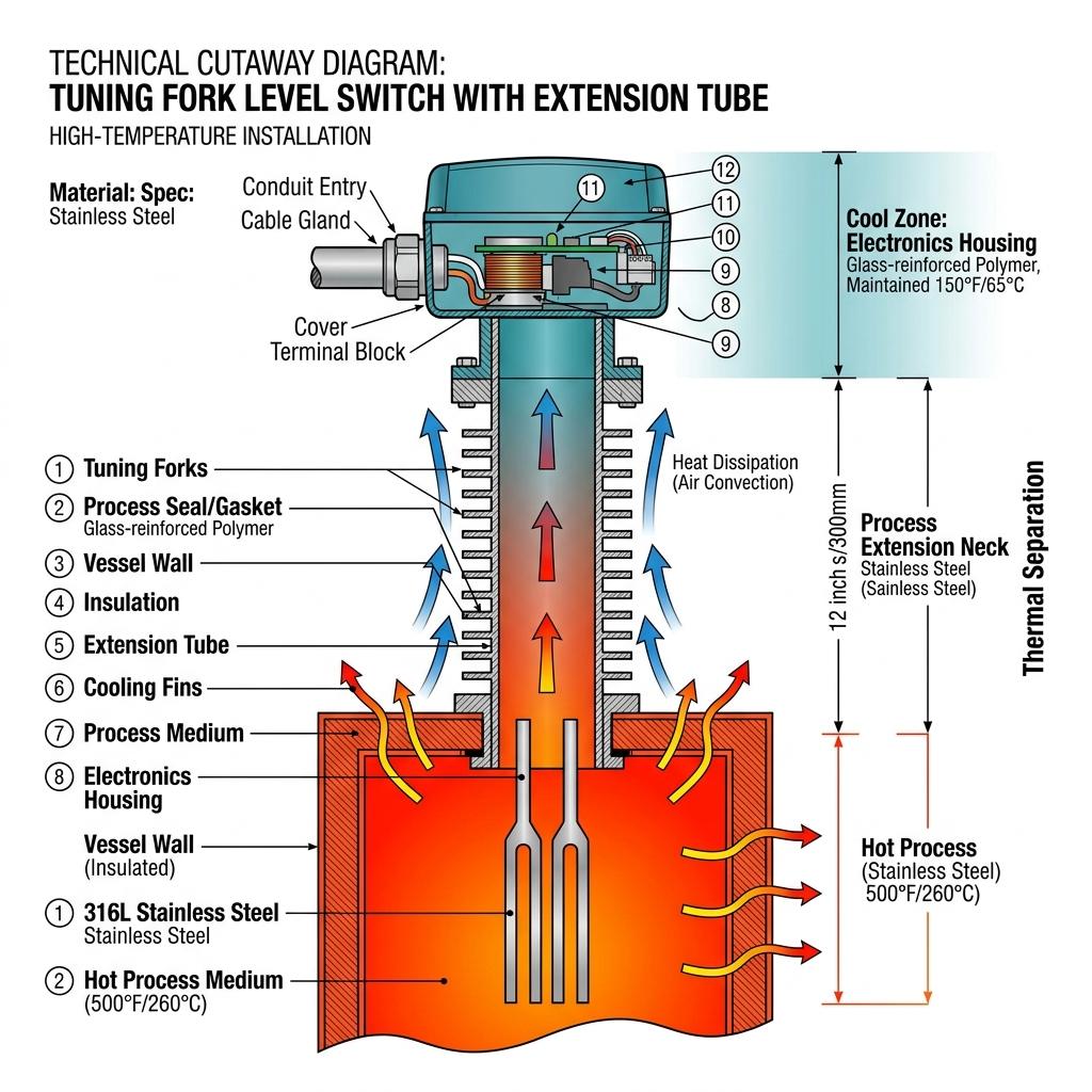
Installation Solution
Use a process extension (neck tube) to create thermal separation between the process and the electronics:
| Temperature Range | Recommended Extension Length | Seal Material |
|---|---|---|
| Up to 100°C | Standard (no extension needed) | NBR gasket |
| 100°C – 150°C | 100–150 mm extension | PTFE gasket |
| 150°C – 200°C | 200+ mm extension | Graphite gasket |
Critical installation steps:
- Never insulate the extension tube. It needs to dissipate heat to ambient air. We once found a maintenance team that wrapped the extension in thermal insulation—the electronics failed within a month.
- Orient the housing upward. Hot air rises; keeping the electronics above the process connection maximizes natural convection cooling.
- Verify seal material compatibility. Standard NBR O-rings degrade above 120°C. Use PTFE or graphite seals for high-temperature service.
- Check the ambient temperature around the housing location—if nearby equipment radiates significant heat, consider remote-mount electronics.
Lessons from the Field: A client running a bitumen storage tank at 170°C experienced intermittent false alarms every afternoon. We discovered the ambient temperature around the electronics housing exceeded 65°C during peak sunlight hours. Adding a simple sun shield and relocating the cable entry to face downward (preventing hot air accumulation inside the housing) eliminated the issue completely.
Scenario 2: Viscous & Sticky Media (Syrups, Resins, Paints)
Typical applications: Food processing (chocolate, honey, sugar syrup), coatings manufacturing, petrochemical slurry tanks.
The Challenge
Viscous materials cling to the fork tines after the level drops. The residual coating dampens vibration, making the switch “think” material is still present—a false high-level indication. This is the single most common failure mode we encounter in the field.
Installation Solution
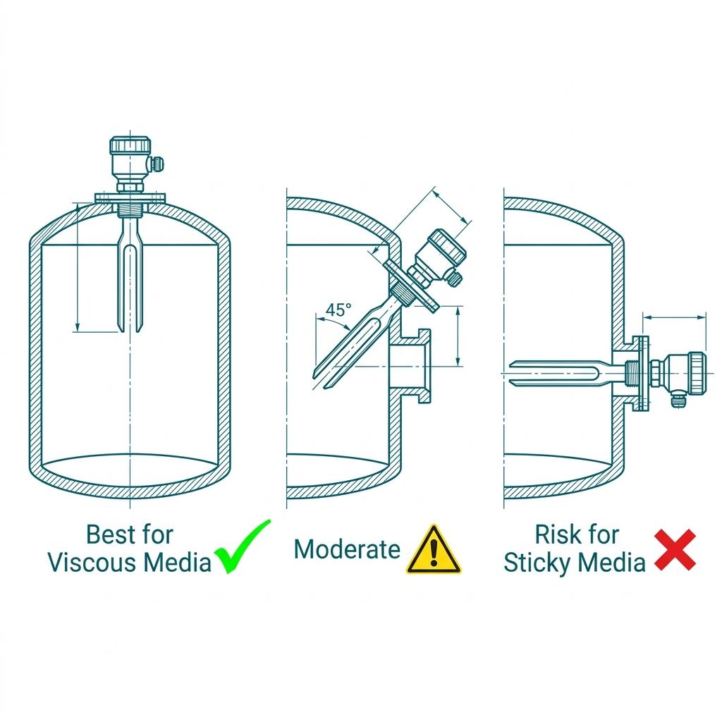
Always install vertically (fork pointing down) for viscous media. Gravity assists material drainage from the tines.
Fork orientation rules for viscous applications:
| Installation | Effectiveness with Viscous Media | Risk |
|---|---|---|
| Vertical (fork down) | ✅ Best—gravity drains material | Low |
| Angled 45° | ⚠️ Marginal—partial drainage | Medium |
| Horizontal (fork sideways) | ❌ Worst—material pools on tines | High |
Additional best practices:
- Choose a fork with large vibration amplitude. Our tuning fork level switch features high-amplitude oscillation specifically designed to shake off low-viscosity hanging materials—preventing the false reading problem that plagues competitors’ low-amplitude designs.
- Align the fork face parallel to the flow direction. This minimizes the surface area that contacts the flowing medium and reduces material deposition.
- Consider the medium’s behavior at rest. Chocolate at 40°C flows easily, but at 25°C it becomes quasi-solid. If your vessel cools during shutdowns, residual material on the fork will harden. Plan for cleaning access during maintenance windows.
Lessons from the Field: A paint manufacturer installed fork level switches horizontally in three mixing tanks. Within one week, all three were showing permanent “high level” despite tanks being empty. Switching to vertical installation and polishing the fork tines to a mirror finish (reducing surface adhesion) solved the problem. No further false alarms in 18 months.
Scenario 3: Corrosive Chemicals (Acids, Alkalis, Solvents)
Typical applications: Chemical processing plants, electroplating facilities, water treatment (chlorine dosing), battery manufacturing.
The Challenge
Standard 316L stainless steel forks resist many chemicals, but concentrated sulfuric acid, hydrofluoric acid, or hot caustic soda can attack even 316L over time. Pitting on fork tines changes the mass distribution, shifting the resonant frequency and causing calibration drift.
Installation Solution
Material selection is your first line of defense:
| Chemical Environment | Fork Material | Seal Material | Coating Option |
|---|---|---|---|
| Mild acids (pH 3–5) | 316L SS | PTFE | None needed |
| Strong acids (HCl, H₂SO₄) | Hastelloy C-276 | PTFE | PFA coating |
| Caustic alkalis (NaOH) | 316L SS | EPDM | None needed |
| Solvents (toluene, acetone) | 316L SS | FKM (Viton) | None needed |
| Hydrofluoric acid | Hastelloy / PVDF-coated | PTFE | PVDF coating |
Critical installation steps:
- Verify chemical compatibility BEFORE installation. Cross-reference your process chemicals with a corrosion resistance chart and contact our engineers for specific media verification.
- Use flanged connections for corrosive service. Threaded connections are harder to inspect and more prone to crevice corrosion.
- Install a process isolation valve between the switch and the vessel. This allows removal for inspection without draining the vessel.
- Inspect the fork tines during scheduled maintenance for pitting, erosion, or coating damage. Run your finger along the tine edges—any roughness you can feel means corrosion has started.
Lessons from the Field: An electroplating facility using hot chromic acid (60°C, pH 1.2) experienced tuning fork failure every 3 months with standard 316L forks. Switching to PFA-coated forks extended the service life to over 2 years—an 8× improvement that paid for the coating upgrade within the first replacement cycle.
Scenario 4: Bulk Solids & Powders (Cement, Grain, Plastic Pellets)
Typical applications: Cement silos, grain elevators, plastic resin hoppers, pharmaceutical powder bins.
The Challenge
Falling powder creates impact force on the fork. Dusty environments can clog the housing vents. Fine powders can bridge across the fork tines, creating a false “material present” condition. And in grain applications, the material density varies between wheat (780 kg/m³) and rice (750 kg/m³)—requiring sensitivity adjustments.
Installation Solution
Mount the switch away from the material fill stream—this is non-negotiable. Install at least 500 mm from any inlet nozzle.
Recommended mounting angles for solids:
| Material Type | Installation Angle | Reason |
|---|---|---|
| Free-flowing granules | Horizontal | Direct contact, fast response |
| Fine powders | 15–30° from horizontal (fork tilted down) | Prevents accumulation on fork |
| Sticky powders | Vertical (fork down) | Gravity-assisted self-cleaning |
| High-density pellets | Horizontal with protective baffle | Prevents impact damage |
Additional best practices:
- Use the automatic learning function. Our tuning fork level switch can learn different medium densities through the key operation—no external calibration equipment needed. This is especially valuable for silos where content changes seasonally (e.g., wheat in summer, corn in autumn).
- Install a protective baffle 200 mm above the switch when mounting near material discharge points. This deflects falling material away from direct fork impact.
- Never confuse a rotary paddle level switch with a tuning fork. Rotary paddles suit heavy bulk solids better; tuning forks excel in powders and light granules where rotary motors would create unnecessary mechanical complexity.
Scenario 5: Agitated Vessels & Turbulent Zones
Typical applications: Mixing reactors, tanks with recirculation pumps, vessels near inlet nozzles.
The Challenge
Mechanical vibration from agitators can interfere with the fork’s resonant frequency detection. You can actually hear this problem during commissioning—place your ear near the housing during agitation, and you’ll hear an irregular humming that differs from the clean, steady tone the fork produces in calm liquid. Turbulence near inlet pipes causes rapid level fluctuations that trigger nuisance alarms. This was the exact problem described in an engineering forum discussion where a tuning fork was positioned adjacent to a pump recirculation nozzle.
Installation Solution
- Maintain minimum distance from vibration sources: Install the tuning fork at least 3× the pipe diameter away from any inlet nozzle, and as far as practically possible from agitator shafts.
- Use the built-in switching delay (time delay function) to filter out turbulence-induced transient signals. A 2–5 second delay eliminates most nuisance trips without compromising safety response time.
- Install in a stilling well (calming tube) if the vessel has severe turbulence. A DN50 or larger pipe welded to the vessel wall provides a calm zone where the fork can measure actual level rather than wave crests. When tapping on the stilling well pipe during installation, you should feel a solid, dampened thud—not a ringing vibration. If it rings, the pipe wall is too thin.
- Consider baffle plates if you cannot relocate the switch away from the agitation zone.
Lessons from the Field: A specialty chemicals client had a 5,000-liter reactor with a high-speed agitator running at 120 RPM. The tuning fork, installed on the side wall 300 mm from the impeller, tripped 4–5 times per batch during agitation. The relay was clicking so fast it sounded like a telegraph machine. We recommended relocating the switch to the opposite side of the vessel and adding a 3-second time delay. Nuisance trips dropped to zero. The client later told us: “We should have called you before the fabrication shop finished the vessel.”
Scenario 6: Hazardous Areas & Safety-Critical Installations
Typical applications: Oil refineries, gas processing plants, chemical storage facilities classified as Zone 1/Zone 2 (IEC) or Division 1/2 (NEC).
The Challenge
Improper installation in hazardous areas risks explosion. Safety instrumented systems (SIS) per IEC 61508 require proven-in-use devices with documented failure rates. The ATEX directive governs equipment for explosive atmospheres in the EU. Electrical connections must meet stringent standards—intrinsic safety barriers, flameproof enclosures, and proper cable glands are mandatory, not optional.
Installation Solution
- Verify explosion-proof certification matches your area classification. Our tuning fork level switches are available with explosion-proof certifications (e.g., Ex d IIB T6) suitable for Zone 1 and Zone 2 applications per the IEC 60079 series. Contact our engineering team to confirm the specific certification for your model.
- Use certified cable glands and conduit seals. The cable entry must be IP67 minimum. Bend cables downward before entry to create a drip loop—moisture inside flameproof enclosures is a common but preventable failure.
- Follow the wiring diagram precisely. Intrinsic safety barriers limit the energy entering the hazardous zone. Using incorrect barrier ratings or exceeding cable length limits compromises the protection concept.
- Document everything for SIS validation—device certification numbers, installation drawings, loop test results, and commissioning records.
For a deeper dive into hazardous area requirements, see our guide on level switch solutions for oil and gas applications.
Installation Orientation Quick Reference
| Scenario | Recommended Orientation | Fork Direction | Mounting |
|---|---|---|---|
| Clean liquids | Any | Any | Thread/Flange |
| Viscous liquids | Vertical | Fork pointing down | Flange |
| Free-flowing solids | Horizontal | Fork into vessel | Thread/Flange |
| Fine powders | 15–30° tilt | Fork angled down | Flange |
| Agitated vessels | Side-mount, far from agitator | Fork perpendicular to flow | Flange |
| High temperature | Vertical (electronics up) | Fork down | Flange with extension |
Troubleshooting Common Installation-Related Problems
| Symptom | Likely Cause | Solution |
|---|---|---|
| Permanent “high level” signal in empty vessel | Material buildup on fork tines | Clean tines; switch to vertical mounting; polish fork surface |
| Permanent “low level” signal when vessel is full | Fork not reaching into material; process connection too long | Verify insertion length; check that material actually contacts the fork |
| Intermittent false alarms | External vibration interference from agitator or pump | Relocate switch; add time delay; install stilling well |
| Signal drift during temperature changes | Electronics overheating; seal degradation | Add process extension; replace seals; install sun shield |
| Switch output not changing | Electrical wiring error; electronics failure | Check power supply voltage; verify output wiring per diagram; test relay |
| Slow response time | Material viscosity too high; switch sensitivity set too low | Adjust sensitivity via auto-learn function; switch to vertical mounting |
| Seal leakage at process connection | Incorrect gasket material for temperature/pressure | Replace gasket with appropriate material; verify torque specification |
| False trips during vessel filling | Switch installed in fill stream | Relocate switch ≥500 mm from fill nozzle; add baffle |
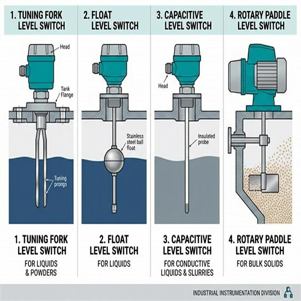
Tuning Fork vs. Other Level Switch Technologies
Understanding when to choose a tuning fork over other technologies helps engineers avoid misapplication:
| Feature | Tuning Fork | Float Switch | Capacitive | Rotary Paddle |
|---|---|---|---|---|
| Moving parts | None | Yes (float) | None | Yes (motor) |
| Viscous media | Good (vertical mount) | Poor (float sticks) | Fair | N/A |
| Corrosive media | Good (coated/alloy options) | Limited | Good | Limited |
| Powders/solids | Good (light powders) | N/A | Fair | Excellent (heavy solids) |
| Calibration needed | No (auto-learn) | Mechanical adjustment | Yes | Mechanical |
| Maintenance | Very low | Medium (moving parts) | Low | Medium (motor) |
| SIL rated | Available (model-dependent) | Rarely | Rarely | Rarely |
| Response time | < 1 second | 1–5 seconds | < 1 second | 1–3 seconds |
Frequently Asked Questions
Can a tuning fork level switch be installed horizontally?
Yes, horizontal installation works well for clean liquids and free-flowing granular solids. However, for viscous media, always install vertically with the fork pointing downward to allow gravity-assisted material drainage from the tines.
What is the maximum temperature a tuning fork level switch can handle?
Standard models typically handle process temperatures up to 150°C. With a process extension neck tube, this range can extend to 200°C or beyond by thermally separating the electronics from the hot process. Always check the specific model’s rated temperature range.
Do tuning fork level switches require calibration?
Modern tuning fork switches like ours feature automatic learning functions that adapt to different medium densities without external calibration. Simply activate the auto-learn feature in the presence of your target medium—the electronics store the reference frequency automatically.
How far should a tuning fork be installed from an agitator?
Install the switch as far as practically possible from the agitator—ideally on the opposite side of the vessel. At minimum, maintain a distance of 3× the inlet pipe diameter from any nozzle. Use a switching time delay of 2–5 seconds to filter turbulence effects.
Can tuning fork level switches detect both liquids and solids?
Yes. Tuning fork level switches reliably detect liquids, slurries, and granular/powder solids. For powders and granules, the sensitivity may need adjustment via the auto-learn function to account for lower bulk density compared to liquids.
What explosion-proof rating do tuning fork level switches have?
Our tuning fork level switches are available with explosion-proof certifications (e.g., Ex d IIB T6) suitable for Zone 1 and Zone 2 hazardous areas. The exact certification varies by model—contact our engineering team to confirm the specific Ex marking and gas group rating for your application.
How is a tuning fork level switch different from a vibrating rod?
A tuning fork uses two tines (like a musical tuning fork) that vibrate against each other, while a vibrating rod uses a single probe. The dual-tine design provides better sensitivity for liquids and light powders, while vibrating rods are typically preferred for heavy bulk solids and materials with high buildup tendency.
Conclusion
Installing a tuning fork level switch in a clean water tank is straightforward. The real engineering challenge—and where experience matters most—is making these switches perform reliably under harsh conditions.
Key takeaways:
- High temperature: Use process extensions and heat-resistant seals—never insulate the extension tube.
- Viscous media: Always mount vertically with the fork down; choose large-amplitude fork designs.
- Corrosive chemicals: Match fork material and coatings to your specific chemical environment.
- Bulk solids: Stay away from fill streams; use baffles and auto-learn sensitivity.
- Agitated vessels: Distance from vibration sources plus time delay eliminates false trips.
- Hazardous areas: Certification matching and proper cable management are non-negotiable.
Every scenario in this guide comes from problems we’ve helped engineers solve in the field. If you’re facing a challenging level switch installation, contact our engineering team—we’ll help you get it right the first time.
Related Articles
- How Do Tuning Fork Level Switches Detect Liquid Levels So Accurately?
- What Are the Best Applications for Tuning Fork Level Switches?
- How to Properly Connect a Level Switch in Your Process System?
- What’s the Key Difference Between Level Switches and Level Transmitters?
- What Are the Main Types of Level Switches in Industrial Applications?
- What Are the Working Principles Behind Level Switches?