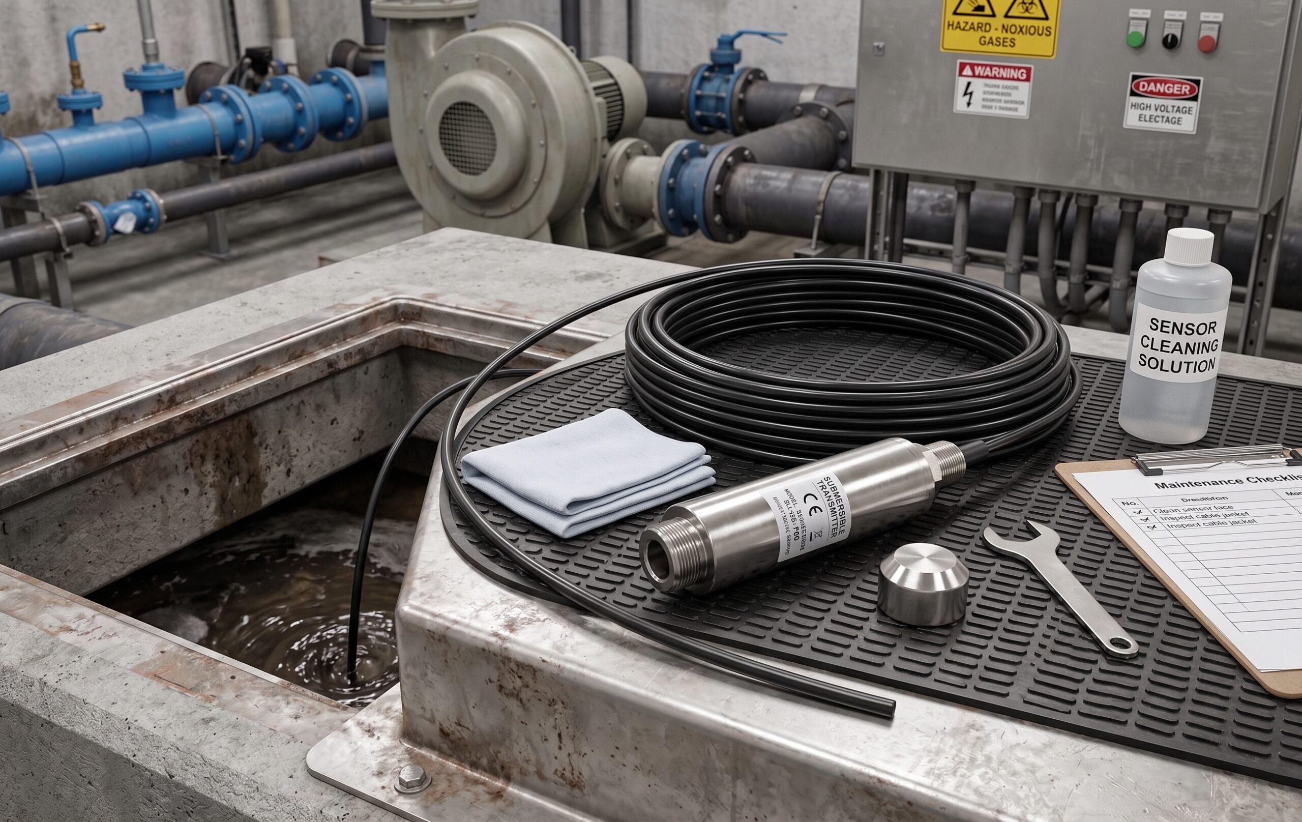
Fig. 1 — A portable ultrasonic flow meter in action: clamp-on transducers attach to the pipe exterior with no pipe cutting or process interruption required.
You’re standing next to a cooling water header in a manufacturing plant, armed only with a carrying case and a 30-minute window. You need to know the actual flow rate through a 200 mm carbon steel pipe—right now—without stopping the line, without calling a pipe fitter, and without drilling a single hole. That’s exactly the job a portable ultrasonic flow meter was built for.
In our experience supporting hundreds of field audits at Soaring Instrument, this is the single most misunderstood product category in flow measurement. Engineers know they need portability. They don’t always know which model fits their pipe material, which transducer mode to choose, or why they keep getting unstable readings after a pump. This guide fixes all of that.
Quick Answer: A portable ultrasonic flow meter measures liquid flow by clamping sensors to the outside of a pipe and timing ultrasonic pulses traveling upstream and downstream through the fluid. No pipe cutting. No process interruption. Battery-powered with 16 hours of continuous operation, it covers DN25–DN1200 pipes (DN15–DN1200 with optional small-pipe transducers) with ±1% accuracy on clean single-phase liquids.
For a broader overview of ultrasonic flow measurement technology, see our pillar guide: The Complete Guide of Ultrasonic Flow Meter
1. What Is a Portable Ultrasonic Flow Meter?
A portable ultrasonic flow meter is a handheld, battery-powered transit-time flow measurement system consisting of:
- A compact transmitter/display unit (IP54 / NEMA13 rated)
- One pair of clamp-on ultrasonic transducers with a magnetic guiding rail with scale markings for quick, accurate spacing
- Acoustic coupling gel (couplant)
- A carrying case with built-in data logger (32G TF card) and PC data analysis software
Unlike fixed wall-mount or panel-mount ultrasonic meters, portable units are designed to be:
- Moved from pipe to pipe — one technician, one briefcase-size kit, dozens of measurement points per day
- Battery operated — 3000 mAh rechargeable lithium battery, ~16 hours of continuous operation without a power outlet
- Fast to set up — enter pipe OD, wall thickness, and material; the meter calculates transducer spacing automatically
- Data logging built-in — 32G TF card auto-records all readings for trend analysis and field reporting
| Parameter | Portable Ultrasonic Flow Meter | Fixed Clamp-On Ultrasonic |
|---|---|---|
| Power Supply | Rechargeable Li-battery 3000mAh | AC 90–245V or DC 24V |
| Battery Life | ~16 hours continuous | N/A (permanent power) |
| Data Logger | Built-in 32G TF card | External / optional |
| Transmitter Protection | IP54 (NEMA13) | IP65 (typical) |
| Transducer Protection | IP68 (encapsulated) | IP68 |
| Pipe Size (standard transducers) | DN25–DN1200 | DN25–DN1200 |
| Pipe Size (with small transducers) | DN15–DN1200 | DN15+ (model-dependent) |
| Best Use Case | Audits, commissioning, verification | Continuous process monitoring |
2. How It Works: Transit-Time Ultrasonic Principle
All of Soaring Instrument’s portable ultrasonic flow meters use the transit-time (time-of-flight) difference method—the gold standard for clean, single-phase liquid measurement.
2.1 The Physics
Two transducers are clamped to the pipe wall at a calculated spacing distance. They alternate between sending and receiving ultrasonic pulses through the fluid:
- Downstream pulse (with the flow direction): Sound travels faster → shorter transit time t_down
- Upstream pulse (against the flow direction): Sound travels slower → longer transit time t_up
The flow velocity is derived from the time difference:
v = K × (t_up − t_down) / (2 × t_up × t_down)Where K is a geometry factor dependent on transducer spacing, pipe diameter, and mounting angle.
Volumetric flow Q is then: Q = v × A (cross-sectional pipe bore area).
Flow range on Soaring Instrument’s portable model: ±0.01 m/s to ±12 m/s (±0.03 ft/s to ±40 ft/s).
2.2 Transducer Mounting Configurations
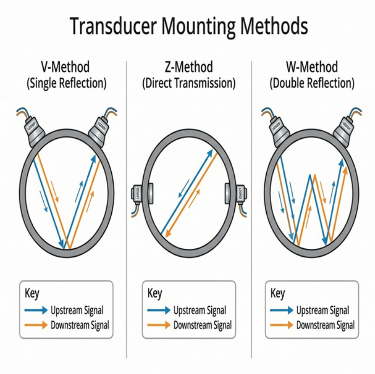
Fig. 2 — Three transducer mounting configurations: V-Method (single reflection, most common), Z-Method (direct transmission, for large or attenuating pipes), and W-Method (double reflection, for small diameter pipes DN15–DN50).
| Method | Description | Best For |
|---|---|---|
| V-Method (single reflection) | Both transducers on the same side; signal bounces off the far pipe wall | DN25–DN300, most common field use |
| Z-Method (direct transmission) | Transducers on opposite sides of the pipe | DN200+; pipes with high signal attenuation (lined, corroded) |
| W-Method (double reflection) | Signal bounces twice; both transducers on same side | DN15–DN50, very small bore pipes |
For more on the transit-time principle in detail: How Does a Transit-Time Ultrasonic Flow Meter Work?
3. Technical Specifications (From Soaring Instrument Product Catalog)
⚠️ All parameters below are taken verbatim from the Soaring Instrument official product catalog. Do not use third-party specifications to describe this product.
3.1 Performance Specifications
| Parameter | Specification |
|---|---|
| Measurement Principle | Transit-time (clamp-on, non-invasive) |
| Flow Range | ±0.01 m/s to ±12 m/s (±0.03 ft/s to ±40 ft/s) |
| Accuracy | ±1% of measured value |
| Pipe Size — Standard Transducers | DN25–DN1200 (1"–48") |
| Pipe Size — With Small Transducers (optional) | DN15–DN1200 (½"–48") |
| Compatible Pipe Materials | Carbon steel, stainless steel, PVC, and other compact solid-wall pipe materials |
| Fluid Type | Single medium liquid (clean, single-phase; not for slurries or multi-phase flow) |
3.2 Function Specifications
| Parameter | Specification |
|---|---|
| Analog Output | 4–20 mA, Max load 750 Ω |
| Digital Communication | Modbus RS485 |
| Data Logger | Built-in 32G TF (SD) card + PC data analysis software |
| Power Supply | Rechargeable Lithium Battery, 3000 mAh |
| Battery Life | ~16 hours continuous operation (main battery) |
| Optional Function | Energy meter (BTU/cold-heat meter): Add RTD module + PT1000 clamp-on temperature sensors |
3.3 Physical Specifications
| Parameter | Specification |
|---|---|
| Transmitter Protection | NEMA13, IP54 |
| Transducer Construction | Encapsulated design, IP68 |
| Transducer Cable Length | Standard: 5 m (16 ft) |
| Transmitter Operating Temperature | −20°C to +60°C |
| Humidity | Up to 99% RH, non-condensing |
3.4 Optional Energy Meter Function
By adding the RTD module and PT1000 clamp-on temperature sensors, the portable flow meter transforms into a full portable energy meter / cold-heat meter (BTU meter) capable of measuring:
- Instantaneous and cumulative thermal energy (kWh, BTU, GJ)
- Supply and return temperatures
- ΔT (temperature differential)
This is particularly valuable for:
- Auditing chilled water loops in data centers and office buildings
- Verifying HVAC heat exchanger performance before commissioning permanent meters
- Energy auditing of industrial cooling and heating systems
See also: How Do Clamp-On Ultrasonic Flow Meters Measure Energy in Different Applications?
4. Key Applications
The portable ultrasonic flow meter is widely used across:
Applications (per product catalog): Oil industry, water treatment, pure water, chemical processing, and more.
4.1 Irrigation System Verification
Irrigation districts often need to verify pump output across remote field locations where running power cables is impractical. The 16-hour battery life covers a full day of site work.
According to Oklahoma State University Extension research on portable ultrasonic flowmeters for irrigation, these instruments achieve 1–5% field accuracy on clean water pipelines when correctly installed — making them the instrument of choice for irrigation efficiency evaluations in remote areas.
External reference: OSU Extension — Review and Operational Guidelines for Portable Ultrasonic Flowmeters
Related: How to Choose the Right Flow Meter for Your Irrigation System?
4.2 Industrial Cooling Water Audits
Factories with multiple cooling loops often have no permanent flow meters installed. A portable unit allows the energy manager to systematically audit each loop, identify hydraulic imbalance, and pinpoint energy waste—all without any investment in permanent meter infrastructure.
Related: How Accurate Are Ultrasonic Flow Meters?
4.3 Pump and Valve Performance Verification
The most common use case we see: a maintenance engineer suspects a pump is underperforming. Instead of a 4-hour planned shutdown and impeller inspection, they clamp a portable ultrasonic meter in place and compare against the pump curve. A 15% flow deficit identified in under 15 minutes.
Catalog note: "Its portability makes it an excellent choice for measuring flows throughout the plumbing infrastructure to verify sensor, pump and valve performance." — Soaring Instrument Product Catalog
4.4 Oil Industry & Water Treatment / Pure Water
From crude oil transfer line verification to treated effluent monitoring and pure water system auditing, the portable meter’s wide pipe diameter range (DN25–DN1200 standard, DN15+ with small transducers) makes it the universal verification tool.
Related: What Are Ultrasonic Flow Meters Used For? | What Fluids Can Ultrasonic Flow Meters Measure?
4.5 Pre-Commissioning of Permanent Clamp-On Meters
Before installing a fixed wall-mount or permanent clamp-on meter, technicians use a portable unit to confirm signal quality at the chosen pipe location. If signal strength is poor due to pipe corrosion or internal scaling, the installation position can be changed before any hardware is mounted.
📌 Lesson from the Field
We had a customer install a fixed clamp-on meter on a 10-year-old cast iron pipe without first verifying signal quality with a portable unit. The heavily corroded pipe interior scattered the ultrasonic signal so badly that the meter read zero intermittently. A 5-minute pre-check with the portable meter would have prevented three weeks of troubleshooting. Always verify signal quality with a portable unit first on older infrastructure.
5. Portable vs. Other Ultrasonic Flow Meter Types
| Feature | Portable (Handheld) | Clamp-On (Fixed) | Insertion Ultrasonic | Inline Ultrasonic |
|---|---|---|---|---|
| Installation | Clamp on (external) | Clamp on (permanent mount) | Pipe penetration required | Inline flange/wafer |
| Pipe Interruption | None | None | Hot-tap possible | Full shutdown needed |
| Portability | ✅ Briefcase-size | ❌ Fixed mount | ❌ Fixed mount | ❌ Fixed inline |
| Battery Operation | ✅ 16 hrs (3000mAh) | ❌ Mains power | ❌ Mains power | ❌ Mains power |
| Data Logger | ✅ Built-in 32G TF | Optional | Optional | Optional |
| Accuracy | ±1% | ±1% | ±1–1.5% | ±0.5–1% |
| Best For | Audits, verification | Continuous monitoring | Large pipe retrofits | Highest-accuracy installs |
For a head-to-head comparison of inline vs. clamp-on designs: What Are the Key Differences Between Inline and Clamp-On Ultrasonic Flow Meters?
6. How to Choose the Right Portable Ultrasonic Flow Meter
Step 1: Confirm Your Pipe Characteristics
- Outer Diameter (OD) and Wall Thickness: Measure on-site with a tape measure and ultrasonic thickness gauge. Nominal pipe schedules often diverge from actual dimensions after years of corrosion or internal scaling.
- Pipe Material: Affects the speed of sound through the pipe wall. Compatible materials per catalog: carbon steel, stainless steel, PVC, and other compact solid-wall pipe materials.
- Internally Lined Pipes (rubber, cement, PTFE): These significantly attenuate the ultrasonic signal. Use Z-method (direct transmission) mounting and increase signal gain (AMP) settings.
- Pipe Size: Standard transducers cover DN25–DN1200. For pipes in the DN15–DN24 range, specify optional small-pipe transducers when ordering.
Step 2: Confirm Your Fluid
| Fluid Condition | Recommended Solution |
|---|---|
| Clean water, oils, chemicals (single-phase) | ✅ Transit-time portable meter — works perfectly |
| Dirty water with >100 ppm particles >100 µm | ⚠️ Consider Doppler-type portable; transit-time accuracy degrades |
| Entrained air / gas bubbles >5% | ❌ Transit-time meters will give erratic readings; purge air first |
| Slurries / high solids | ❌ Use electromagnetic flow meter instead |
| Pure water / ultrapure water | ✅ Transit-time portable meters are ideal (no conductivity requirement) |
Related: What Type of Ultrasonic Flow Meter is Best for Clean Fluids?
Step 3: Confirm Straight Pipe Availability
This is the most common source of field measurement error. The portable meter requires a fully developed, symmetric velocity profile to achieve ±1% accuracy.
| Installation Condition | Min. Upstream Straight Run | Min. Downstream Run |
|---|---|---|
| General (single elbow in-plane) | ≥ 10D | ≥ 5D |
| Two elbows (out-of-plane, 3D swirl) | ≥ 25D | ≥ 5D |
| After a partially-open valve | ≥ 30D | ≥ 10D |
| After a pump | ≥ 20D | ≥ 10D |
| After pipe expansion/reduction | ≥ 30D | ≥ 5D |
D = pipe internal diameter. These are minimum requirements; always use more if available.
Related: Pipe Requirements for Ultrasonic Flow Meter Installation | Why Proper Upstream/Downstream Piping is Critical for Clamp-On Ultrasonic Meters?
Step 4: Do You Need Energy Metering?
If you need to measure heat or cold consumption (kWh, BTU, GJ), specify the optional RTD module + PT1000 clamp-on temperature sensor upgrade. The portable flow meter becomes a complete portable energy auditing station—critical for HVAC and thermal system commissioning.
Related: What Are The Key Applications of Clamp-On Ultrasonic BTU Meters?
7. Step-by-Step Installation Guide
- Select the measurement point. Choose a section of straight pipe meeting the upstream/downstream requirements above. For horizontal pipes, mount transducers at the 3 o’clock or 9 o’clock position — never at 12 o’clock (risk of air accumulation at top) or 6 o’clock (risk of sediment buildup at bottom).
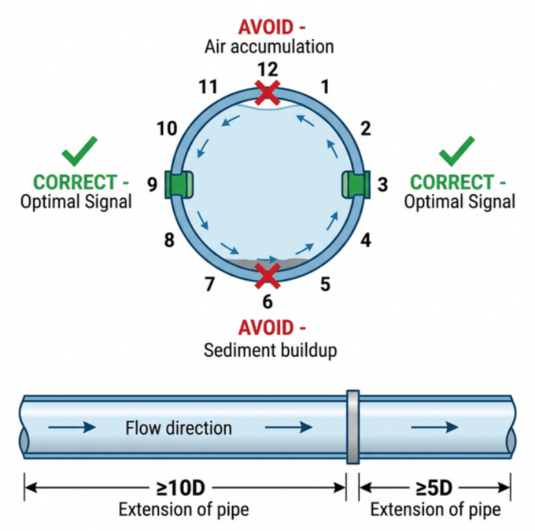
Fig. 3 — Correct mounting position on horizontal pipes (3 or 9 o’clock) and minimum straight pipe run requirements for accurate measurement.
Measure and enter pipe parameters. Use a tape measure for OD and an ultrasonic thickness gauge for wall thickness. Enter both into the meter menu before calculating spacing. A 1 mm error in wall thickness input can introduce 1–3% measurement error.
Let the meter calculate transducer spacing. The magnetic guiding rail has printed scale markings. Set the distance exactly as displayed on the meter — do not estimate.
Apply coupling gel. Apply a bead of acoustic couplant (silicone grease preferred; axle grease is an acceptable substitute) to the transducer face. Press the transducer against the pipe and slide it gently forward — the gel should spread uniformly with no air bubbles trapped underneath. Never skip the coupling gel — without it, the ultrasonic signal is almost entirely reflected at the pipe surface and never enters the fluid.
See: What Is Ultrasonic Flow Meter Coupling Gel and Why Is It Important?
Lock transducers using the magnetic clamp. Tighten until finger-firm. Do not over-tighten — excessive torque slightly warps the transducer face, breaking full acoustic contact and causing erratic readings.
Check signal quality (Q value / Signal Strength indicator). Target: ≥60% signal strength. If below threshold, try: increasing AMP gain one level; repositioning transducers 5–10 cm along the pipe axis; or switching from V-method to Z-method on attenuating pipe materials.
Perform zero-point calibration if needed. Zero the meter with the pipe fluid completely still. This eliminates static thermal gradient offset inside the pipe wall. Per the Soaring SR7 manual: "Must be performed with fluid completely at rest."
Begin logging. The 32G TF card logs all data automatically. Export to PC using the included data analysis software for reporting.
💡 Pro Tip from Our Field Technicians
On older painted or corroded pipes, grind or sand a 5 × 5 cm patch of the pipe surface at each transducer location until you reach bare metal. In our field testing, this single step reduces signal noise by 30–50% and dramatically stabilizes readings on pipes older than 10 years. The small paint-free zone can be repainted after testing.
For complete wiring and output configuration: How to Calculate and Set Up an Ultrasonic Flow Meter Correctly?
8. Troubleshooting Guide
| Symptom | Likely Cause | Solution |
|---|---|---|
| Zero reading / Q = 0 | No acoustic contact; gel air gap; pipe too attenuating | Re-apply gel; re-seat transducers; increase AMP gain; try Z-method |
| Erratic / fluctuating readings | Entrained air; insufficient straight run; mechanical vibration | Bleed air from pipe; relocate 10D+ from fittings; dampen pipe vibration |
| Consistent 10–20% under-reading | Internal scaling/corrosion; incorrect wall thickness entered | Re-measure wall thickness with ultrasonic gauge; try Z-method |
| Unstable readings near pump | Pump-induced turbulence and swirl | Move ≥20D upstream from pump; use Z-method across the pipe |
| No signal on plastic/lined pipe | High signal attenuation in pipe material | Use lower-frequency transducers; switch to Z-method (direct path) |
| Reading drift over time (hot conditions) | Gel drying out; thermal expansion causing transducer slip | Re-apply fresh gel every 3–4 hours; use coupling pad instead of gel in extreme heat |
| Error after valve | Flow profile distorted by partial closure | Move ≥30D downstream of valve; ensure valve is fully open |
Full guides:
- How to Troubleshoot Ultrasonic Flow Meter Signal Loss?
- Why Is My Ultrasonic Flow Meter Not Working? Expert Solutions
- Clamp On Ultrasonic Flow Meter Troubleshooting Checklist
9. Advantages and Limitations
✅ Key Advantages
- Zero process interruption — no pipe cutting, no system shutdown required
- True field portability — briefcase-size, 16-hour battery runtime, works anywhere — remote fields, high floors, outdoor installations
- Wide pipe diameter coverage — DN25–DN1200 (standard) / DN15–DN1200 (with optional small transducers)
- No moving parts — zero wear, zero maintenance on moving components; sensors simply clamp to the pipe exterior
- No pressure drop — completely non-invasive; ideal for low-pressure systems
- Built-in data logging — 32G TF card auto-records for long-term trend analysis and automated reports
- Upgradeable to energy meter — add optional RTD + PT1000 sensors for kWh / BTU measurement
- Compatible with multiple pipe materials — carbon steel, stainless steel, PVC, and other compact solid-wall materials
- Sound waves penetrate safely — no fluid contact, no contamination risk; ideal for pure water, chemicals, food-grade systems
Related: What are the advantages and disadvantages of Ultrasonic flow meters?
⚠️ Key Limitations
- Clean single-phase fluids only (transit-time) — not suitable for slurries, high-solids flows, or heavily aerated liquids
- Requires adequate straight pipe — ≥10D upstream minimum; accuracy near zero at pipe fittings
- Pipe must be 100% full — partial fill causes severe errors (the meter calculates flow using assumed full cross-sectional area)
- Not ideal for highly attenuating pipes — thick cast iron, heavily corroded interiors, cement-lined pipes reduce signal quality
- Coupling gel is not permanent — in high-temperature or high-vibration environments, gel migrates or dries; re-application needed during long sessions
10. Frequently Asked Questions (FAQ)
Q1: What is a portable ultrasonic flow meter?
A portable ultrasonic flow meter is a handheld, battery-powered device that measures liquid flow in pipes using the transit-time ultrasonic method. Clamp-on transducers are clamped to the outside of the pipe — no pipe cutting, no tapping, no process interruption required. Soaring Instrument’s model includes a 3000 mAh battery (16 hours continuous), built-in 32G TF data logger, and optional energy meter function.
Q2: How accurate are portable ultrasonic flow meters?
When correctly installed on clean, full pipes with adequate straight runs, Soaring Instrument portable transit-time meters achieve ±1% of measured value. OSU Extension field research demonstrated real-world accuracy of 1–12% variance depending on installation quality — confirming that proper transducer placement, coupling gel application, and straight pipe selection are critical to achieving rated accuracy.
Q3: What pipe sizes can portable ultrasonic flow meters measure?
Soaring Instrument’s portable model covers DN25–DN1200 (1"–48") with the standard transducer set. By adding optional small-pipe transducers, coverage extends to DN15–DN1200 (½"–48"). One set of standard transducers is sufficient for the full DN25–DN1200 range — a key advantage for multi-pipe audit work.
Q4: How long does the battery last?
The built-in rechargeable 3000 mAh lithium battery delivers approximately 16 hours of continuous operation. The unit can also operate while charging if a power supply (generator, AC outlet) is available at the field site.
Q5: Can a portable ultrasonic flow meter measure dirty or aerated water?
Transit-time portable flow meters (including Soaring Instrument’s model) require clean, single-medium liquid. For water containing significant particulates (Doppler-favorable) or for slurries and wastewater with high solids content, an electromagnetic flow meter is more appropriate. For slightly aerated water, purge the air first and verify the pipe is 100% full before measuring.
Q6: What is coupling gel and why is it essential?
Acoustic coupling gel fills the microscopic air gaps between the transducer face and the pipe surface. Without it, the ultrasonic signal is almost entirely reflected at the metal-air interface and never enters the pipe or fluid. Silicone grease is the preferred couplant; axle grease is an acceptable field substitute. Apply fresh gel each time a transducer is repositioned.
Q7: What upstream and downstream straight pipe length do I need?
Standard minimum requirement: ≥10D upstream and ≥5D downstream of any elbow, fitting, or flow disturbance. After a pump: ≥20D upstream. After a partially-open or control valve: ≥30D upstream. These values are based on established flow measurement standards and Soaring Instrument installation guidelines.
Conclusion
A portable ultrasonic flow meter is the right tool when:
- You need to measure multiple pipe locations that change over time
- Your fluid is a clean, single-phase liquid (water, cooling fluid, oil, chemicals)
- The site has no permanent power supply
- You need to verify flow before committing to a permanent meter installation
- You need to audit HVAC or cooling system energy consumption (with optional RTD/PT1000 upgrade)
For permanent continuous process monitoring, a fixed wall-mount clamp-on ultrasonic or inline ultrasonic flowmeter provides more reliable long-term data.
Get a Quote
Ready to measure flow without stopping your process?
Contact Soaring Instrument to select the right portable ultrasonic flow meter model for your pipe size, fluid type, and application — with or without the optional energy meter upgrade.
📧 Contact Soaring Instrument
✉️ [email protected]
📞 0086-13585991410
Related Articles
- The Complete Guide of Ultrasonic Flow Meter
- Clamp On Ultrasonic Flow Meter: The Complete Guide to Non-Invasive Flow Measurement
- How Accurate Are Ultrasonic Flow Meters?
- What Makes Handheld Ultrasonic Flow Meters Essential for Field Measurements
- Pipe Requirements for Ultrasonic Flow Meter Installation
- How to Install a Clamp On Ultrasonic Flow Meter: Step-by-Step Guide
- What Are The Key Applications of Clamp-On Ultrasonic BTU Meters?
- Why Proper Upstream/Downstream Piping is Critical for Clamp-On Ultrasonic Meters?
- How to Troubleshoot Ultrasonic Flow Meter Signal Loss?
- What Are the Real-World Limitations of Clamp-On Ultrasonic Flow Meters?
Published by Shanghai Soaring Instrument Technology Co., Ltd. | soaringinstrument.com | [email protected]