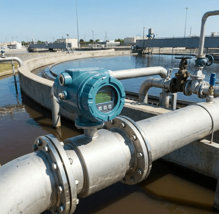
High-reliability electromagnetic flow meter installed on a wastewater treatment plant sludge line
"We tried a vortex flow meter on our return activated sludge line. It worked for about 3 months before the shedder bar was completely wrapped in fibrous debris. Cleaning it became a weekly nightmare."
This story from a municipal wastewater plant operator in Zhejiang Province reflects a pattern we see repeatedly. Before switching to magnetic flow meters, plants experiment with cheaper alternatives—and learn the hard way why electromagnetic flow meters dominate wastewater applications worldwide.
Quick Answer: Magnetic flow meters have no moving parts and no obstructions in the flow path. Unlike turbine meters (rotating parts wear out) or vortex meters (bluff bodies clog), mag meters provide a completely open pipe that handles raw sewage, sludge, and debris-laden water without clogging or maintenance issues.
The Core Problem: Wastewater Is Brutally Hard on Flow Meters
Wastewater isn’t just dirty water. It’s a complex mixture that destroys most flow measurement technologies:
| Challenge | Impact on Flow Meters |
|---|---|
| Suspended solids | Abrasion, clogging, signal interference |
| Fibrous debris (rags, hair, wipes) | Wraps around anything protruding into flow |
| Variable viscosity | Sludge consistency changes hourly |
| Corrosive chemicals | Chlorine, acids, industrial effluents attack materials |
| Biological growth | Biofilm accumulation on sensor surfaces |
| Air bubbles | Entrained air from aeration processes |
Traditional flow meters simply cannot survive these conditions long-term. According to the U.S. Environmental Protection Agency (EPA), accurate flow measurement is critical for compliance with National Pollutant Discharge Elimination System (NPDES) permits—making meter reliability a regulatory necessity, not just an operational preference.
Let’s examine why each alternative fails—and why magnetic flow meters succeed.
What Magnetic Flow Meters Replace (And Why)
Turbine Flow Meters: The Rotating Parts Problem
Turbine flow meters use spinning rotors to measure flow. In clean water applications, they work well. In wastewater:
| Issue | Consequence |
|---|---|
| Bearings wear from grit | Accuracy degrades within months |
| Fibrous debris wraps the rotor | Rotor stalls, no reading |
| Solids impact the blades | Physical damage, catastrophic failure |
| Requires regular disassembly | High maintenance labor costs |
Reality: We’ve seen turbine meters in wastewater applications require complete replacement every 6-12 months. At $500-2000 per meter plus labor, this adds up quickly.
Vortex Flow Meters: The Shedder Bar Disaster
Vortex flow meters rely on a bluff body (shedder bar) that protrudes into the flow to create vortices. In wastewater:
| Issue | Consequence |
|---|---|
| Debris accumulates on shedder bar | Flow signal becomes erratic |
| Fibrous materials wrap around bar | Blocks vortex formation entirely |
| Grease/fat buildup changes geometry | Accuracy drift |
| Cleaning requires process shutdown | Production losses |
Reality: The shedder bar is the exact worst shape for wastewater—it catches everything. Plants using vortex meters on sludge lines often schedule weekly or even daily cleaning.
Differential Pressure Flow Meters: Clogging Guaranteed
Orifice plates, venturi tubes, and other differential pressure meters involve restrictions that measure flow by pressure drop. In wastewater:
| Issue | Consequence |
|---|---|
| Solids accumulate upstream of restriction | Increasing pressure drop, false readings |
| Impulse lines and sensing ports clog | Complete measurement failure |
| Cannot handle varying solid content | Accuracy varies with sludge concentration |
Reality: DP meters require constant maintenance of impulse lines and regular cleaning of primary elements. Most wastewater plants abandoned them decades ago.
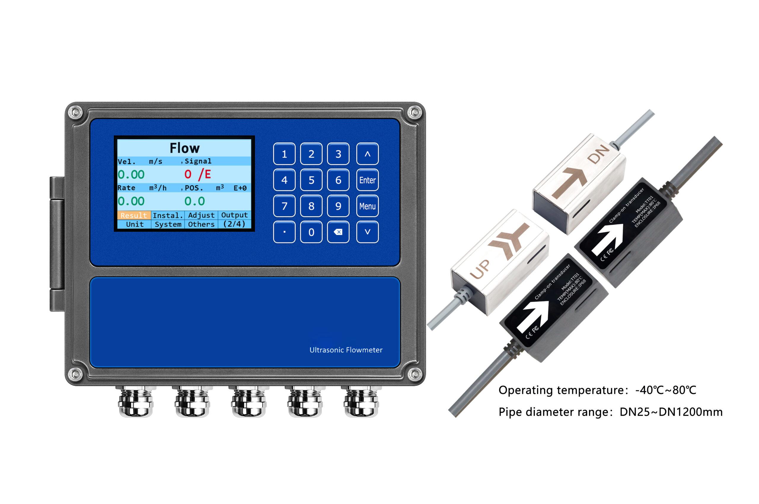
Ultrasonic Flow Meters: The Solids Limitation
Ultrasonic flow meters are excellent for clean liquids. However, transit-time ultrasonic meters require acoustic signal transmission through the fluid:
| Issue | Consequence |
|---|---|
| Suspended solids scatter ultrasonic signals | Signal loss, no reading |
| High solids concentration blocks transmission | Complete failure in sludge |
| Bubbles from aeration interfere with signals | Erratic readings |
Exception: Doppler ultrasonic meters actually require particles in the flow and can work on some wastewater applications. However, they offer lower accuracy (typically ±2-5%) compared to mag meters (±0.5% or better).
Why Magnetic Flow Meters Dominate: The Physics
Magnetic flow meters operate on Faraday’s Law of electromagnetic induction. As described in the Wikipedia article on electromagnetic flow meters, when a conductive liquid moves through a magnetic field, it generates a voltage proportional to the flow velocity:
E = B × D × V
Where:
- E = induced voltage
- B = magnetic field strength
- D = pipe diameter
- V = flow velocity
Why This Matters for Wastewater
The key insight: the measurement happens across the entire pipe cross-section, with nothing protruding into the flow.
| Feature | Wastewater Benefit |
|---|---|
| No moving parts | Nothing to wear, break, or require lubrication |
| No protrusions | Nothing for debris to catch on or wrap around |
| Full-bore design | Same internal diameter as connected pipe = no restriction |
| Zero pressure drop | No energy loss—critical for gravity-fed systems where every pascal matters |
| Wide range coverage | From DN3 to DN3000, handling flows from trickling to torrential |
| Immune to viscosity | Works the same on water or thick sludge |
| Immune to density changes | Solids concentration doesn’t affect measurement |
| Bidirectional capability | Measures forward and reverse flow equally |
The bottom line: A magnetic flow meter is essentially an "invisible" measurement—the flow doesn’t even know the meter is there.
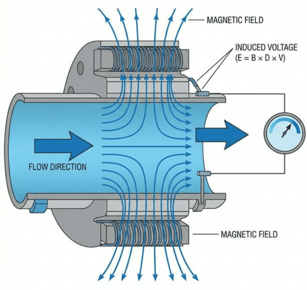
Figure 2: Faraday’s Law in action – induced voltage is proportional to flow velocity through the magnetic field
Wastewater Treatment Plant Applications
Magnetic flow meters are deployed throughout the entire wastewater treatment process:
Primary Treatment
| Location | Purpose | Typical Pipe Size |
|---|---|---|
| Influent flow | Total plant inflow monitoring, regulatory reporting | DN200-DN1000+ |
| Grit chamber discharge | Flow balance control | DN50-DN200 |
| Primary sludge line | Sludge production measurement | DN80-DN200 |
Secondary Treatment
| Location | Purpose | Typical Pipe Size |
|---|---|---|
| Return Activated Sludge (RAS) | Process control, recirculation ratio | DN100-DN400 |
| Waste Activated Sludge (WAS) | Solids inventory management | DN50-DN200 |
| Mixed liquor feeds | Aeration basin flow distribution | DN150-DN400 |
Tertiary Treatment & Effluent
| Location | Purpose | Typical Pipe Size |
|---|---|---|
| Filter feed/backwash | Filter loading optimization | DN100-DN300 |
| Chemical dosing | Chlorine, polymer, nutrient dosing control | DN15-DN50 |
| Final effluent | Discharge permit compliance | DN200-DN1000+ |
Sludge Processing
| Location | Purpose | Typical Pipe Size |
|---|---|---|
| Thickener feed/discharge | Sludge concentration control | DN80-DN200 |
| Digester feed | Organic loading rate control | DN100-DN300 |
| Dewatering feed | Press/centrifuge loading | DN50-DN150 |
Technical Specifications for Wastewater Applications
Based on our product line, here are the key specifications for wastewater applications:
Performance Specifications
| Parameter | Specification |
|---|---|
| Applicable Media | Conductive liquid (min. ≥20 µS/cm) |
| Accuracy | ±0.5% of reading (standard); ±0.3% or ±0.2% (optional) |
| Flow Velocity Range | 0.1-15 m/s |
| Turndown Ratio | 150:1 |
| Response Time | ≤1 second |
Physical Specifications
| Parameter | Specification |
|---|---|
| Pipe Diameter (Pipeline) | DN3-DN3000 |
| Pipe Diameter (Insertion) | DN100-DN3000 |
| Max Working Pressure | 42 MPa (pipeline type) |
| Medium Temperature | -40°C to +180°C |
| Protection Class | IP65, IP68 |
| Explosion-proof | ExdIIa, ExdII CT6 Gb |
Output & Communication
| Parameter | Specification |
|---|---|
| Analog Output | 4-20mA |
| Digital Output | RS-485, HART |
| Pulse/Frequency Output | Available |
| Display | Four-line LCD |
| Alarm Output | Relay dry contact, up to 2 channels |
Material Selection for Wastewater: A Critical Decision
Choosing the right liner and electrode materials is essential for long-term reliability in wastewater applications.
Liner Material Selection
| Liner Material | Best Applications | Temperature Range | Notes |
|---|---|---|---|
| PTFE | Chemical wastewater, high-temp | -40°C to +180°C | Best chemical resistance |
| F46 (FEP) | General wastewater, corrosive | -40°C to +120°C | Good all-around choice |
| PFA | Ultrapure to aggressive chemicals | -40°C to +160°C | Premium option |
| Rubber (Neoprene/EPDM) | Abrasive slurries, sludge | -10°C to +65°C | Best abrasion resistance (available upon request) |
Recommendation for typical municipal wastewater: Rubber liner for sludge lines; PTFE or F46 for chemical dosing and corrosive streams.
Electrode Material Selection
| Electrode Material | Best Applications | Key Advantage |
|---|---|---|
| SUS316L Stainless Steel | General wastewater, clean water | Cost-effective, good general resistance |
| Hastelloy B | Reducing acids (hydrochloric, phosphoric) | Superior acid resistance |
| Hastelloy C | Oxidizing acids, chlorine-containing | Best oxidizing environment resistance |
| Titanium | Seawater, chloride-rich wastewater | Excellent chloride resistance |
| Tungsten Carbide Coated | Highly abrasive slurries | Maximum abrasion resistance |
Recommendation for typical municipal wastewater: SUS316L for general applications; Hastelloy C for chlorinated effluent; Tungsten Carbide for abrasive sludge.
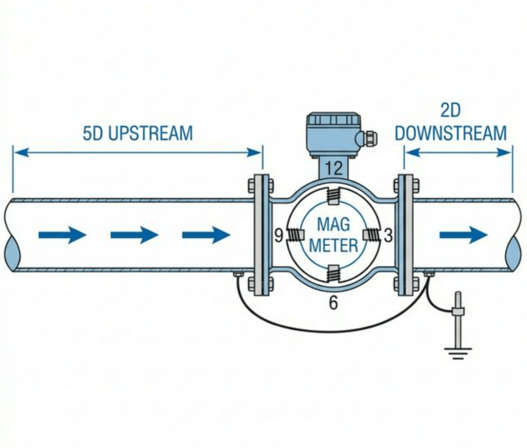
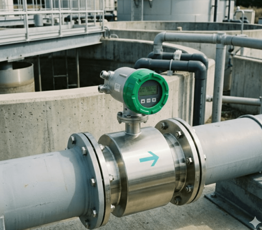
Figure 3: Proper installation with horizontal electrode orientation on a DN300 sludge line
Conductivity: The One Requirement
Unlike mechanical flow meters, magnetic flow meters require the fluid to be electrically conductive. The minimum conductivity requirement is ≥20 µS/cm.
Wastewater Conductivity Reality Check
| Wastewater Type | Typical Conductivity | Suitable for Mag Meter? |
|---|---|---|
| Municipal raw sewage | 500-1500 µS/cm | ✅ Yes, easily |
| Secondary effluent | 300-1000 µS/cm | ✅ Yes |
| Activated sludge | 800-2000 µS/cm | ✅ Yes |
| Industrial pretreatment | 200-5000+ µS/cm | ✅ Yes (varies by industry) |
| Stormwater | 50-500 µS/cm | ✅ Yes (above threshold) |
| RO reject | 2000-10000+ µS/cm | ✅ Yes |
| Pure water (for reference) | 1-5 µS/cm | ❌ No (too low) |
Key Point: Virtually all wastewater types exceed the 20 µS/cm threshold by a large margin. Conductivity is rarely a concern in wastewater applications.
Installation Best Practices
Proper installation maximizes accuracy and reliability. Key considerations for wastewater:
Straight Pipe Requirements
| Configuration | Upstream | Downstream |
|---|---|---|
| After elbow/bend | 5D | 2-3D |
| After partially open valve | 10D | 2-3D |
| After pump | 10D | 2-3D |
| After reducer | 5D | 2-3D |
D = pipe diameter
Orientation
- Horizontal installation: Preferred; electrodes should be positioned horizontally (at 3 and 9 o’clock positions) to prevent air bubble accumulation
- Vertical installation: Acceptable with upward flow to ensure pipe is always full
- Avoid: Vertical installation with downward flow (empty pipe risk)
Grounding
Proper grounding is essential, especially in wastewater plants with plastic (HDPE, PVC) piping:
- Use grounding rings or grounding electrodes
- Connect to plant ground system
- Verify ground resistance <10Ω
What installation actually feels like: When you bolt on the flanges of a DN200 rubber-lined mag meter to a sludge line, there’s a reassuring heft to the sensor body—about 15kg for this size. The rubber liner has a slightly springy give when you press it, and you can feel the quality in the smooth bore. As you tighten the flange bolts in a star pattern, you’ll notice the gasket compressing evenly. Power it up, and within 30 seconds the LCD displays stable readings—no calibration, no adjustment. That moment when raw sludge starts flowing through and the meter reads steady at 45 m³/h without a flicker? That’s when you know you’ve solved the plant’s measurement problems for the next two decades.
Case Study: Municipal WWTP Upgrade (2024)
Client: 100,000 m³/day municipal wastewater treatment plant, Jiangsu Province
Timeline: October 2023 – December 2024 (14-month monitoring period)
Challenge:
- 15 existing vortex flow meters on sludge lines required cleaning every 2-3 days
- 2 technicians spent ~50% of time on flow meter maintenance
- Unreliable flow data made process optimization impossible
Solution:
- Replaced all 15 vortex meters with electromagnetic flow meters
- Selected rubber-lined sensors with Hastelloy C electrodes
- Installed insertion-type mag meters on DN400+ lines for cost efficiency
Results after 2 years:
- ✅ Zero clogging incidents – compared to ~120/year previously
- ✅ Maintenance reduced by 95% – annual savings of ~1,500 labor hours
- ✅ Process control improved – reliable RAS ratio optimization saved 12% aeration energy
- ✅ ROI achieved in 8 months – from maintenance savings alone
"The mag meters just work. We check them during annual shutdowns, but they’ve never needed intervention. Our operators can now focus on process optimization instead of meter cleaning." — Plant Manager
Troubleshooting Common Issues
| Problem | Possible Cause | Solution |
|---|---|---|
| No signal/zero reading | Empty pipe | Ensure pipe is full; install at low point or add back pressure |
| Erratic readings | Air bubbles | Check for leaks; install at location with positive pressure |
| Drifting readings | Electrode coating/fouling | Clean electrodes; consider self-cleaning electrode option |
| Low accuracy | Inadequate straight run | Increase upstream straight pipe or install flow conditioner |
| Grounding alarm | Poor grounding | Check grounding rings; verify ground connection |
For detailed troubleshooting guidance, see our magnetic flow meter troubleshooting guide.
Frequently Asked Questions
What is the minimum conductivity for magnetic flow meters in wastewater?
The minimum conductivity requirement is ≥20 µS/cm. Municipal wastewater typically has conductivity of 500-1500 µS/cm—well above this threshold. Learn more about conductivity effects.
Can magnetic flow meters measure sludge?
Absolutely. Mag meters excel at sludge measurement because they have no obstructions that could clog and are immune to viscosity and solids concentration changes. See our guide on the best flow meter for sludge.
How long do magnetic flow meters last in wastewater applications?
With proper liner and electrode material selection, electromagnetic flow meters typically last 15-20+ years in wastewater applications. Learn about electromagnetic flow meter life expectancy.
Do magnetic flow meters require calibration in the field?
Mag meters maintain calibration extremely well because they have no mechanical parts that wear. Most installations only require verification (not recalibration) every 2-5 years. See our calibration guide.
Can I install a magnetic flow meter on a large pipe without shutting down?
Yes. Insertion-type electromagnetic flow meters can be hot-tapped into pipes DN100-DN3000 without process shutdown, making them ideal for retrofits on large mains.
Are battery-powered options available for remote locations?
Yes. Our battery-operated electromagnetic flow meters use five 3.6V lithium batteries and operate continuously for 5-10 years. They’re ideal for remote manholes or locations without power supply.
Conclusion
For wastewater treatment applications, magnetic flow meters are the clear winner:
| Feature | Mag Meter | Turbine | Vortex | Ultrasonic |
|---|---|---|---|---|
| No clogging | ✅ | ❌ | ❌ | ⚠️ |
| No wear parts | ✅ | ❌ | ✅ | ✅ |
| Handles sludge | ✅ | ❌ | ❌ | ⚠️ |
| Zero pressure drop | ✅ | ❌ | ❌ | ✅ |
| Accuracy on dirty fluids | ±0.5% | Degrades | Degrades | ±2-5% |
| Maintenance needs | Minimal | High | High | Low |
The obstruction-free design, immunity to viscosity and solids, and exceptional long-term reliability make magnetic flow meters the default choice for any wastewater flow measurement application.
Ready to Upgrade Your Wastewater Flow Measurement?
Whether you’re designing a new wastewater treatment facility or replacing failing meters at an existing plant, our application engineers can help you select the right magnetic flow meter configuration.
Contact us for a free application review
View our complete Electromagnetic Flow Meter product line
Related Articles
- How Electromagnetic Flow Meters Improve Efficiency in Wastewater Treatment
- What Is The Best Flow Meter For Sludge?
- Can Electromagnetic Flow Meters Handle Corrosive or Abrasive Fluids?
- How Electromagnetic Flowmeters Work: Faraday’s Law in Action
- Does Conductivity Affect Magnetic Flow Meter?
- Electrode Materials Face-Off: Titanium vs. Hastelloy vs. Platinum
- What Maintenance Is Required for Electromagnetic Flow Meters?
- What Is A Flow Meter In Wastewater Treatment?
- Magnetic Flow Meter Troubleshooting: Simple Fixes for Common Problems