"We installed three electromagnetic flow meters on our DI water return lines. None of them worked. The readings were completely erratic—jumping from zero to max scale randomly."
This frustrated call from a semiconductor fab engineer in Taiwan is one we hear regularly at Soaring Instrument. And every time, the diagnosis is the same: you can’t measure ultrapure water with a mag meter.
Quick Answer: Ultrapure water (UPW) has a conductivity of only 0.055 µS/cm—far below the ≥20 µS/cm minimum required for electromagnetic flow meters. Clamp-on ultrasonic flow meters are the only reliable, non-invasive solution for measuring ultrapure water in semiconductor and pharmaceutical applications.
Understanding the technical reason behind this limitation—and why ultrasonic flow meters solve it—is essential for anyone working in high-purity water systems.
The Conductivity Problem: Why Electromagnetic Flow Meters Fail
Electromagnetic flow meters work by applying Faraday’s Law of electromagnetic induction. When a conductive liquid passes through a magnetic field, it generates a voltage proportional to the flow velocity:
E = B × D × V
Where:
- E = induced voltage
- B = magnetic field strength
- D = pipe diameter
- V = flow velocity
The key word here is conductive. For a mag meter to detect any signal at all, the fluid must have a minimum conductivity—typically ≥20 µS/cm according to our product specifications.
The Ultrapure Water Challenge
| Water Type | Conductivity | Resistivity | Suitable for Mag Meter? |
|---|---|---|---|
| Tap water | 200-800 µS/cm | 1.25-5 kΩ·cm | ✅ Yes |
| Distilled water | 1-5 µS/cm | 0.2-1 MΩ·cm | ⚠️ Marginal |
| Deionized (DI) water | 0.5-3 µS/cm | 0.3-2 MΩ·cm | ❌ No |
| Ultrapure water (UPW) | 0.055 µS/cm | 18.2 MΩ·cm | ❌ Impossible |
Ultrapure water—the kind used in semiconductor wafer cleaning and pharmaceutical Water for Injection (WFI) systems—has been stripped of virtually all ions. According to industry standards like ASTM D5127 and SEMI F63, semiconductor-grade UPW must achieve a resistivity of >18.2 MΩ·cm. Its conductivity of 0.055 µS/cm is 363 times lower than the minimum threshold for electromagnetic flow meters.
In simple terms: Trying to use a mag meter on UPW is like trying to hear a whisper in a jet engine—the signal simply doesn’t exist.
Why Ultrasonic Flow Meters Work for Ultrapure Water
Ultrasonic flow meters operate on a completely different principle—one that doesn’t require conductivity at all.
The Transit-Time Principle
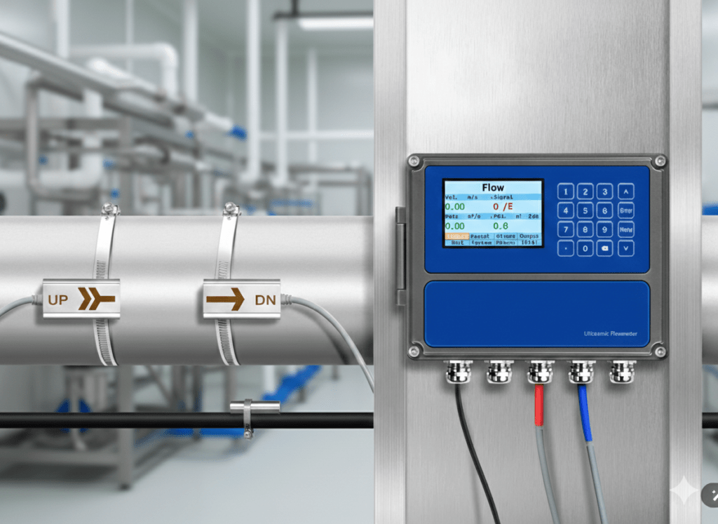
Transit-time ultrasonic flow meters use two transducers that send ultrasonic pulses through the fluid in opposite directions:
- Downstream pulse: Travels faster (assisted by flow)
- Upstream pulse: Travels slower (opposed by flow)
The time difference between these pulses is directly proportional to the flow velocity:
Δt = (2 × L × V × cos θ) / c²
Where:
- Δt = transit time difference
- L = path length
- V = flow velocity
- θ = transducer angle
- c = speed of sound in fluid
The critical point: This measurement depends on the acoustic properties of the fluid—not its electrical conductivity. Ultrapure water has excellent acoustic transmission properties, making it ideal for ultrasonic measurement.
Unlike turbine flow meters that use spinning rotors (which can shed particles into UPW), ultrasonic technology relies entirely on advanced signal processing algorithms. Modern digital signal processing (DSP) chips analyze the transit-time data at over 300 measurements per second, providing exceptionally stable flow metering even at very low velocities.
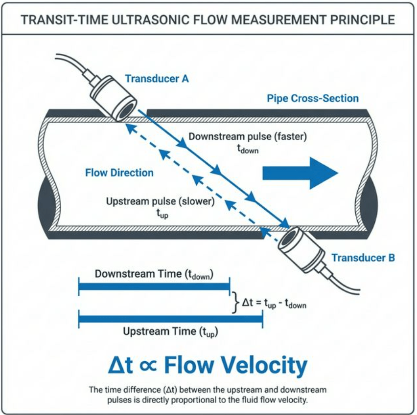
Figure 2: Transit-time ultrasonic measurement principle – upstream and downstream pulses travel at different speeds through the flowing liquid
Clamp-On Design: Zero Contamination Risk
For high-purity applications, the clamp-on configuration offers a decisive advantage: the transducers mount on the outside of the pipe, never touching the fluid.
| Feature | Inline (Wetted) Meter | Clamp-On Ultrasonic |
|---|---|---|
| Fluid contact | Yes | No |
| Contamination risk | Possible | Zero |
| Pipe cutting required | Yes | No |
| Downtime for installation | Hours to days | Minutes |
| Cleanroom integrity | Compromised during install | Maintained |
In semiconductor fabs and pharmaceutical cleanrooms where a single particle can ruin a wafer or contaminate a batch, non-invasive measurement isn’t just convenient—it’s essential.
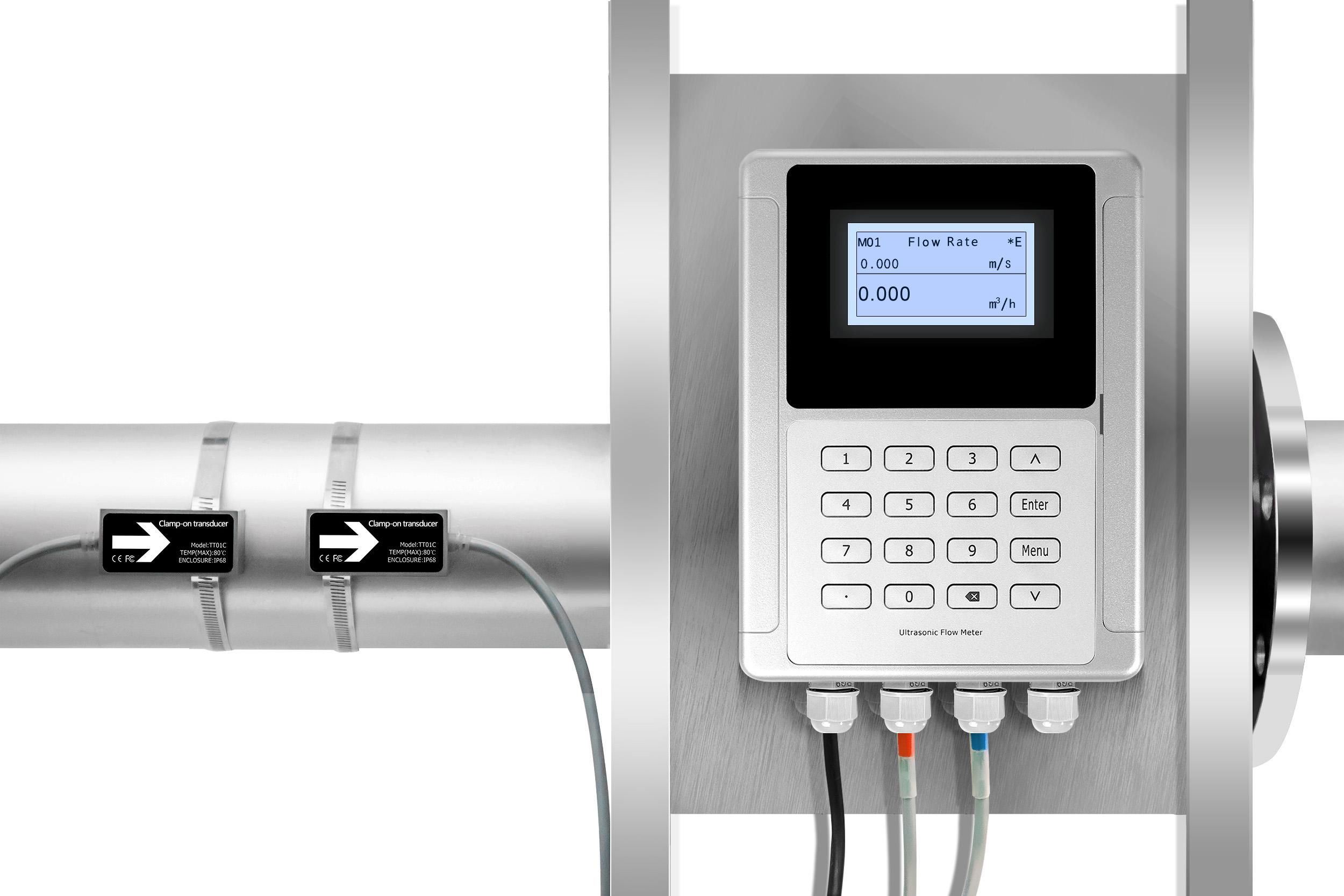
What installation actually feels like: When you clamp the transducers onto a DN50 PVDF pipe, there’s a satisfying click as the mounting bracket locks into position. You’ll feel the slight give of the silicone coupling compound compressing between the transducer face and the pipe wall. Within 30 seconds, the 240×128 LCD display starts showing stable readings—no tools, no cutting, no need to don cleanroom bunny suits. Compare that to the full-day pipe modification required for inline meters and you understand why fab engineers prefer clamp-on.
Industry-Specific Requirements
Semiconductor Manufacturing (FAB)
In semiconductor manufacturing, ultrapure water is used for:
- Wafer rinsing after chemical processes
- Chemical Mechanical Planarization (CMP) post-polish rinse
- Photoresist development
- Final wafer cleaning before packaging
UPW Quality Standards (SEMI F63):
| Parameter | Requirement |
|---|---|
| Resistivity | >18.2 MΩ·cm |
| Conductivity | <0.055 µS/cm |
| TOC | <1 ppb |
| Particles (>0.05µm) | <1/mL |
| Bacteria | <1 CFU/1000 mL |
| Dissolved silica | <0.2 ppb |
Any flow measurement technology that contacts the UPW risks introducing contamination. Clamp-on ultrasonic meters eliminate this risk entirely.
Pharmaceutical WFI Systems
Water for Injection (WFI) is critical in pharmaceutical manufacturing for:
- Injectable drug formulation
- Equipment cleaning and sterilization
- Bulk medicine preparation
WFI Quality Standards (USP/EP):
| Parameter | USP Requirement | EP Requirement |
|---|---|---|
| Conductivity | <1.3 µS/cm (25°C) | <1.1 µS/cm (20°C) |
| TOC | <500 ppb | <500 ppb |
| Endotoxin | <0.25 EU/mL | <0.25 EU/mL |
| Microbial count | <10 CFU/100 mL | <10 CFU/100 mL |
While pharmaceutical WFI has slightly higher conductivity than semiconductor UPW, it’s still too low for electromagnetic flow meters. And in a cGMP environment, the zero-contamination benefit of clamp-on meters is equally critical.
Clamp-On Ultrasonic Flow Meter Technical Specifications
Based on our product catalog, here are the key specifications for ultrapure water applications:
Performance Specifications
| Parameter | Specification |
|---|---|
| Technology | Transit-time difference (TGA) |
| Accuracy | ±1% of measured value (clamp-on); ±2% (±1% after calibration, small pipe type) |
| Repeatability | 0.2% of measured value |
| Linearity | ±1% |
| Flow Velocity Range | ±0.03 m/s to ±12 m/s |
| Measurement Rate | >300 times/second |
| Bubble/Impurity Tolerance | Up to 5 seconds continuous |
Physical Specifications
| Parameter | Specification |
|---|---|
| Pipe Size | DN25-DN1200 (standard); DN15-DN40 (small pipe) |
| Compatible Pipe Materials | Stainless steel, Carbon steel, PVC, PVDF, PP |
| Transmitter Protection | IP65 |
| Transducer Protection | IP68 (true waterproof) |
| Transducer Cable Length | Standard 9m / Maximum 300m |
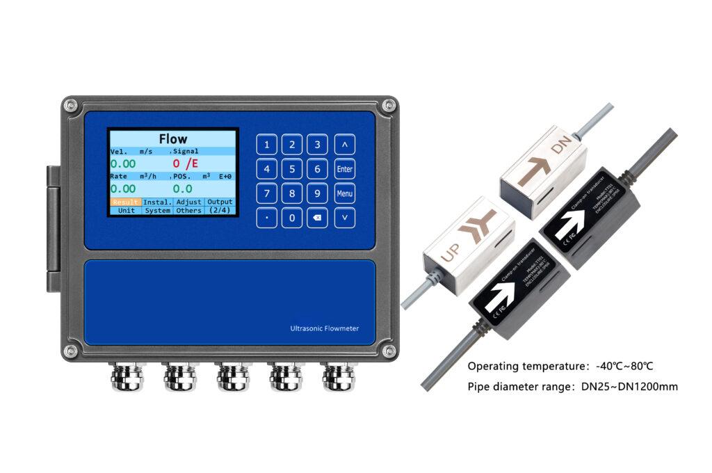
| Operating Temperature | -40°C to +80°C (standard); -40°C to +130°C (high-temp) |
Output & Communication
| Parameter | Specification |
|---|---|
| Analog Output | 4-20mA (max load 750Ω) |
| Pulse Output | 0-10 kHz (for flow switches & totalizers) |
| Communication | RS232/RS485 Modbus (M-BUS, HART optional) |
| Power Supply | DC 10-36V / AC 90-245V |
| Display | 240×128 backlit LCD |
Optional Function: Energy Meter / BTU Meter
Our Clamp-On Ultrasonic Flow Meter can be paired with PT1000 RTD temperature sensors to function as a complete energy meter. This is particularly valuable for:
- Monitoring cooling water energy consumption in semiconductor fabs
- Tracking chilled water usage in pharmaceutical cleanrooms
- Measuring BTU for HVAC systems
The system calculates thermal energy transfer using flow rate and temperature differential—without any wetted connections that could contaminate your UPW system.
Optional Transducers for Different Applications
| Transducer Model | Pipe Range | Temperature Range | Recommended Application |
|---|---|---|---|
| TT01/TT02 | DN25-DN1200 | -40°C to +80°C | General UPW systems |
| TT03 | DN25-DN1200 | -40°C to +130°C | Hot WFI loops |
| TT02H | DN25-DN1200 | -40°C to +180°C | Extreme high-temp applications |
| TT05 (Insertion) | DN25-DN1200 | -40°C to +130°C | Insertion-type for large pipes |
| TT02S | DN15-DN40 | 0°C to +65°C | Small-bore UPW lines |
| TT03S | DN15-DN40 | 0°C to +115°C | High-temp small pipes |
Installation Best Practices for UPW Applications
Pipe Material Compatibility
For ultrapure water systems, the most common pipe materials are:
- PVDF (Polyvinylidene fluoride) – semiconductor fabs
- 316L Stainless Steel – pharmaceutical WFI loops
- PVC – general DI water distribution
All of these are excellent for ultrasonic signal transmission. The key is ensuring:
- Pipe wall is in good condition – no internal scaling or deposits
- Straight run requirements are met – typically 10D upstream, 5D downstream
- Pipe is always full – essential for transit-time measurement
Mounting Considerations
| Configuration | When to Use | Notes |
|---|---|---|
| V-method | DN25-DN300 | Signal crosses pipe once; standard choice |
| Z-method | DN200+ | Signal crosses straight through; better for large pipes |
| W-method | DN15-DN100 | Signal crosses twice; better for small pipes |
For small-bore UPW lines (DN15-DN40), our small pipe ultrasonic flow meters with specialized TT02S/TT03S transducers provide optimal signal quality.
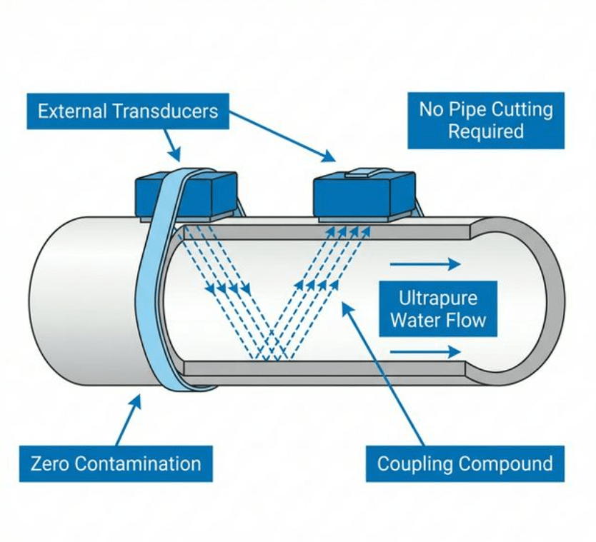
Figure 3: Clamp-on installation – transducers mount externally, eliminating contamination risk in ultrapure water systems
Case Study: Semiconductor Fab UPW Return Monitoring
Client: Major memory chip manufacturer in Jiangsu Province, China
Challenge:
- 12 UPW return lines (DN50 PVDF pipe) required flow monitoring
- Existing variable-area flow meters were causing particle shedding
- Electromagnetic flow meters had been tried and failed (no signal)
Solution:
- Installed 12 clamp-on ultrasonic flow meters with TT02 transducers
- Non-invasive installation completed during scheduled maintenance window
- No pipe cutting, no cleanroom contamination
Results after 18 months:
- ✅ 100% uptime – zero maintenance required
- ✅ Particle counts unchanged – no contamination from meters
- ✅ ±1.5% accuracy verified against volumetric calibration tanks
- ✅ Process control improved – real-time UPW consumption data enabled optimization
"We finally have reliable flow data on our UPW returns. The clamp-on ultrasonic meters just work—no calibration drift, no maintenance, no contamination concerns." — Process Engineer, Fab 3
Troubleshooting: Common Issues in UPW Applications
| Problem | Possible Cause | Solution |
|---|---|---|
| No reading / weak signal | Poor acoustic coupling | Clean pipe surface; use fresh coupling gel |
| Erratic readings | Air bubbles in line | Ensure pipe is always full; check degasser system |
| Signal drops during low flow | Below velocity threshold | Verify flow >0.03 m/s; consider smaller pipe section |
| Temperature compensation error | Transducer temp out of range | Use TT03 high-temp transducers for hot loops |
| Drifting readings | Transducer movement | Re-secure mounting clamps; verify alignment |
For detailed troubleshooting guidance, see our complete ultrasonic flow meter troubleshooting guide.
Frequently Asked Questions
Can I use electromagnetic flow meters for DI water?
It depends on the conductivity. Standard electromagnetic flow meters require ≥20 µS/cm. Some specialty low-conductivity mag meters can work down to 5 µS/cm, but they still cannot measure true ultrapure water (0.055 µS/cm). For UPW applications, ultrasonic is the only reliable choice.
What accuracy can I expect from a clamp-on ultrasonic meter on UPW?
Our clamp-on ultrasonic flow meters achieve ±1% of measured value with 0.2% repeatability. For UPW applications where the acoustic properties are consistent and stable, real-world accuracy is typically even better than the rated specification.
Do clamp-on meters work on small-bore UPW pipes (DN15-DN40)?
Yes. We offer specialized small-pipe transducers (TT02S/TT03S) specifically designed for DN15-DN40 pipes. These provide reliable measurement even on the small-diameter supply lines common in semiconductor tool hookups.
How do I maintain a clamp-on ultrasonic meter in a cleanroom?
Maintenance is minimal because the transducers never contact the process fluid. Periodic checks include:
- Verify transducer coupling compound hasn’t dried out (annually)
- Confirm transducers haven’t shifted (after any nearby work)
- Run a zero-flow check to verify calibration (semi-annually)
See our complete maintenance guide for ultrasonic flow meters.
Can ultrasonic meters handle the high-purity chemicals used alongside UPW?
Clamp-on meters handle any liquid that transmits ultrasonic signals and doesn’t require conductivity. This includes most high-purity chemicals used in semiconductor and pharmaceutical processing. However, for wetted ultrasonic meters, material compatibility with aggressive chemicals must be verified.
What’s the difference between transit-time and Doppler ultrasonic meters for UPW?
Transit-time meters are the correct choice for UPW. Doppler meters require particles or bubbles in the fluid to reflect the ultrasonic signal—which is exactly what you’re trying to eliminate in ultrapure water. Transit-time technology measures the time difference of sound pulses traveling through the clean fluid.
Conclusion
For measuring ultrapure water in semiconductor fabs and pharmaceutical facilities, clamp-on ultrasonic flow meters offer an unmatched combination of:
- ✅ Works regardless of conductivity – no minimum threshold required
- ✅ Zero contamination risk – transducers never touch the fluid
- ✅ Non-invasive installation – no pipe cutting, no downtime
- ✅ High accuracy – ±1% with 0.2% repeatability
- ✅ Minimal maintenance – no wetted parts to clean or replace
The bottom line: if you’re struggling with erratic readings, failed mag meters, or contamination concerns in your UPW system, clamp-on ultrasonic flow measurement is the proven solution.
Ready to Solve Your UPW Flow Measurement Challenge?
At Soaring Instrument, we’ve helped dozens of semiconductor fabs and pharmaceutical facilities transition from failed mag meter installations to reliable ultrasonic measurement.
Contact our application engineers for:
- Application review and sizing assistance
- Trial unit evaluation
- Custom transducer selection for your pipe configuration
View our complete Ultrasonic Flow Meter product line
Related Articles
- What Is the Difference Between Electromagnetic and Ultrasonic Flow Meters?
- Does Conductivity Affect Magnetic Flow Meter?
- What Type of Ultrasonic Flow Meter is Best for Clean Fluids?
- Precision Matters: The Role of Ultrasonic Flow Meters in Small Pipe Applications
- Can Clamp-On Ultrasonic Flow Meters Work Effectively on Small Pipes?
- How Accurate Are Ultrasonic Flow Meters?
- Pipe Requirements for Ultrasonic Flow Meter Installation