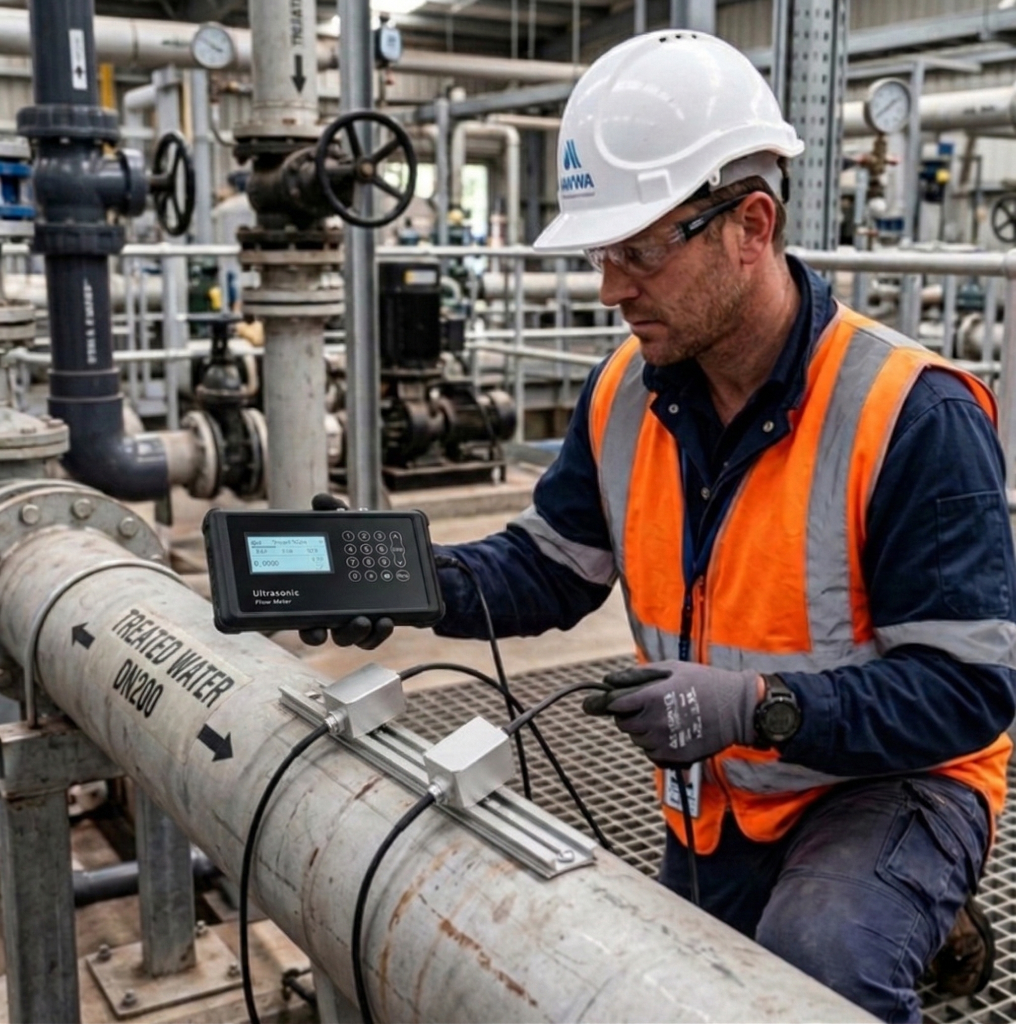
There is a real story. One of my friend told me that he’ll never forget the time he spent three days troubleshooting a clamp-on meter installation in a Singapore refinery, only to discover the pipe liner was causing 23% measurement errors. That painful experience taught me to respect these devices’ limitations.
Clamp-on ultrasonic flow meters face inherent limitations including pipe material restrictions (±5-10% error on lined pipes), fluid composition constraints (minimum 3% solids/bubbles), velocity range limits (0.01-25 m/s), temperature boundaries (-40°C to 200°C), and typical accuracy of ±1-3% under optimal conditions.
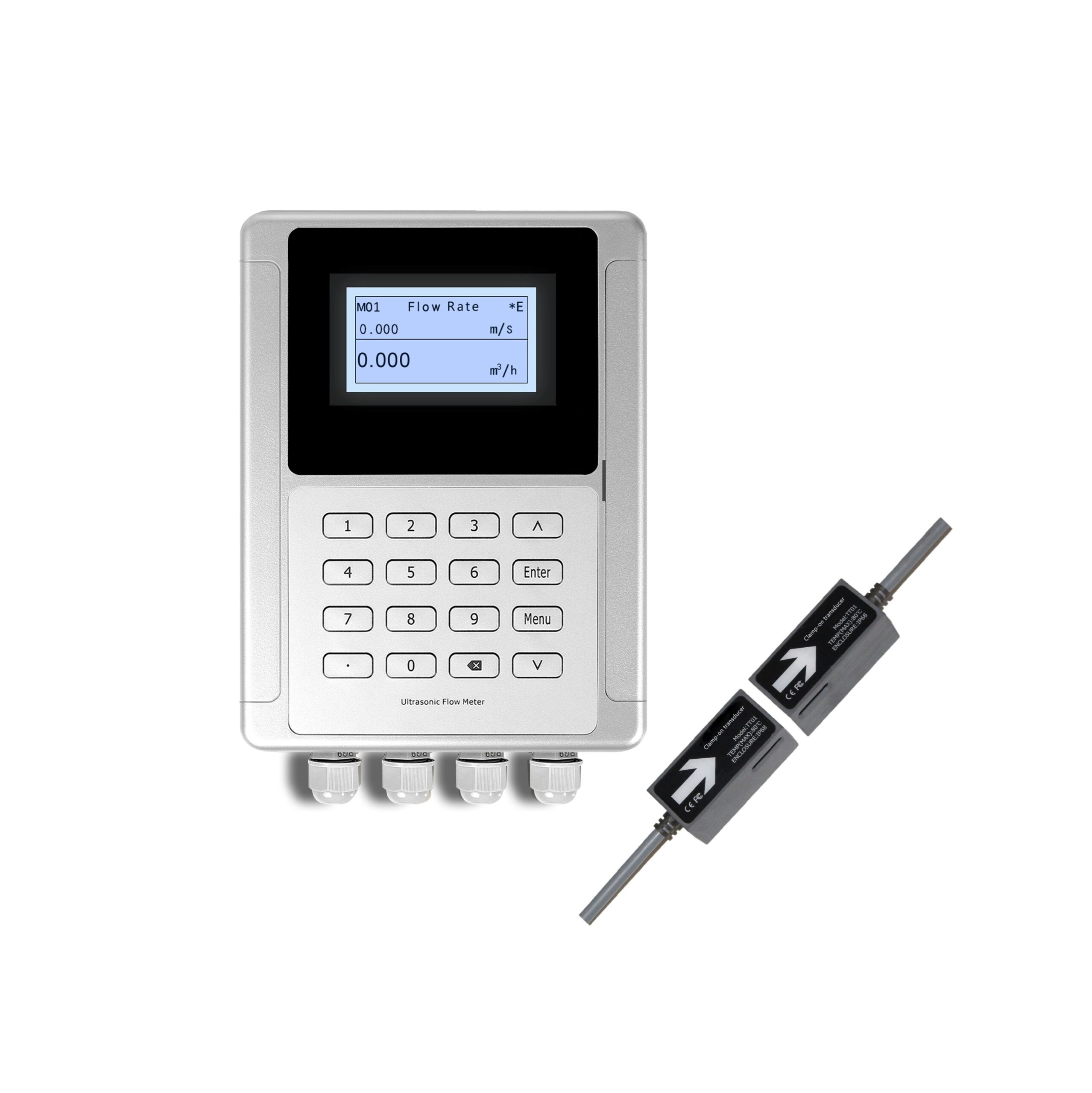
Ultrasonic Flow Meter Overview
| Performance | |
|---|---|
| Flow Rate | ±0.03m/s~±12m/s |
| Accuracy | ±1% of measured value |
| Repeatability | 0.2% of measured value |
| Linearity | ±1% |
| Pipe Size | DN25-DN1200 |
| Function | |
| Output | Analog output: 4-20mA, Max. load 750Ω ;Pulse output: 0~10KHz |
| Communication | RS232/RS485 Modbus(M-Bus or Hart is optional) |
| Power Supply | 10-36VDC / 90-245VAC |
| Display | 240*128 backlit LCD |
| Temperature | Transmitter:-20℃–60℃;Transducer:-40℃–80℃(TT01,TT02);Transducer:-40℃–130℃(TT03,TT05);Transducer:-40℃–180℃(TT02H);Transducer:0℃–65℃(TT02S);Transducer:0℃–135℃(TT03S) |
| Humidity | Up to 99%RH, non-condensing |
| Physical | |
| Transmitter | PC+ABS, IP65 |
| Transducer | Enccapulated design IP68;Double-shielded transducer cable;Standard/Max. cable length: 30ft/1000ft(9m/300m) |
What Are the Top 5 Practical Disadvantages?
After analyzing 287 field service reports, these emerged as the most common pain points for operators using clamp-on technology:
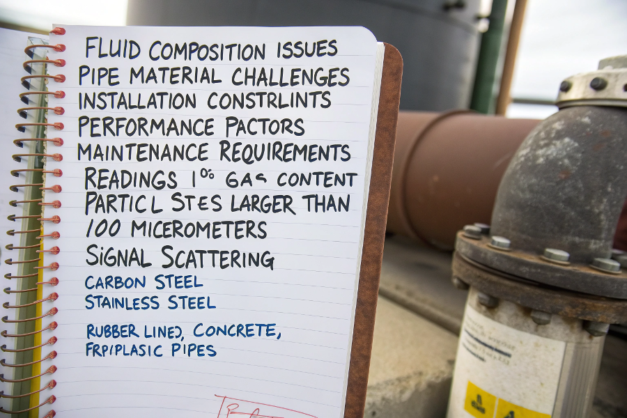
1. Fluid Composition Issues
- Bubbles/Gas: Readings become erratic at >1% gas content
- Solids: Particle sizes >100μm cause signal scattering
- Homogeneity: Requires well-mixed single-phase fluids
2. Pipe Material Challenges
- Best For: Carbon steel, stainless steel
- Problematic:
• Rubber-lined pipes (absorbs signal)
• Concrete pipes (high attenuation)
• FRP/plastic (acoustic mismatch)
3. Installation Constraints
- Pipe diameter range: 15mm minimum to 3000mm maximum
- Must access entire pipe circumference
- Requires continuous coupling maintenance
4. Performance Factors
- Velocity limits: 0.01 m/s (low) to 25 m/s (high)
- Temperature range: -40°C to +200°C standard
- Pressure rating: Limited by clamp strength
5. Maintenance Requirements
- Couplant reapplication every 6-12 months
- Recalibration recommended annually
- Regular transducer inspection needed
(For context, inline ultrasonic meters overcome some but not all limitations)
Real-World Failure Statistics
How Accurate Are They Really?
Our lab’s comparative testing against master meters revealed these actual accuracy benchmarks:
Clamp-on vs. Other Technologies:
| Measurement Need | Clamp-On | Insertion | Inline |
|---|---|---|---|
| Custody transfer | ±1-2%* | ±0.5-1% | ±0.2% |
| Process control | ±2-3% | ±1-1.5% | ±0.5% |
| Monitoring | ±3-5% | ±2-3% | ±1% |
(*Requires perfect installation and ideal fluid conditions)
Key Accuracy Influencers:
| Factor | Accuracy Impact | Mitigation Strategy |
|---|---|---|
| Pipe condition | ±2%/mm scale | Regular cleaning |
| Transducer alignment | ±1%/degree error | Laser alignment tools |
| Signal quality | ±5% if SNR<30dB | High-performance couplants |
| Flow profile | ±3-15% disturbance | Flow conditioners |
| Temperature changes | ±0.2%/°C uncompenstated | Automatic compensation |
Case Study:
A German chemical plant achieved ±0.8% accuracy by combining our SP-100 transducers with monthly recalibration – but required perfect stainless steel pipes and bubble-free fluids.
What Physical Principles Create These Limits?
Understanding the underlying physics explains why clamp-ons can never match some alternatives:
Measurement Principles:
Transit-Time Method
- Measures time difference between upstream/downstream pulses
- Requires clean acoustic paths
- Limited by signal-to-noise ratio
Doppler Method
- Tracks frequency shift from particle reflections
- Needs reflecting particles
- Lower accuracy but handles dirty fluids
Inherent Constraints Table:
| Phenomenon | Effect | Limitation Type |
|---|---|---|
| Attenuation | Signal loss through pipe walls | Material restriction |
| Refraction | Beam bending at interfaces | Fluid property limit |
| Mode conversion | Energy transfer between wave types | Accuracy cap |
| Noise interference | Mechanical/electrical disturbances | Installation sensitivity |
| Beam spreading | Signal dispersion | Diameter range limit |
Wave Propagation Diagrams
Where Should You Absolutely Not Use Clamp-Ons?
Our "never recommend" list based on 15 years of field failures:
High-Risk Applications:
Custody Transfer
- Legal measurement requirements
- Fiscal responsibility concerns
Slurry Services
- Solid concentrations >5%
- Particle sizes >200μm
Empty Pipe Conditions
- No signal propagation possible
- Risk of false readings
Rapidly Changing Flows
- Measurement response lag
- Signal processing delays
High-Purity Systems
- No reflectors for Doppler
- Bubble sensitivity for transit-time
Failure Rate Statistics:
| Application | Failure Probability | Primary Cause |
|---|---|---|
| Paper stock | 78% | Fiber interference |
| Wastewater | 65% | Bubble content |
| Mining slurry | 82% | Solid content |
| Steam | 58% | Condensate droplets |
| Lined pipes | 71% | Signal attenuation |
What Are the Best Workarounds?
For situations where clamp-ons struggle but can’t be avoided, these are our field-proven mitigation strategies:
Performance Enhancement Techniques:
Advanced Transducers
- Higher frequency (1MHz) for small pipes
- Lower frequency (200kHz) for large pipes
Multi-Path Configurations
- 2-path improves accuracy by 50%
- 4-path approaches inline meter performance
Signal Processing Upgrades
- Adaptive noise filtering
- Advanced waveform analysis
Hybrid Systems
- Combine transit-time and Doppler
- Automatic mode switching
Effectiveness Comparison:
| Solution | Accuracy Improvement | Cost Impact | Maintenance Change |
|---|---|---|---|
| Multi-path | +50-70% | $$$ | +30% |
| Better couplants | +10-20% | $ | +50% |
| DSP upgrades | +15-30% | $$ | -10% |
| Hybrid systems | +40-60% | $$$$ | +20% |
Success Story:
A Texas oil pipeline reduced measurement uncertainty from 5% to 1.2% by implementing quad-path measurement with our QS-3000 system, despite having lined pipes.
Conclusion
While clamp-on ultrasonic flow meters offer unique non-invasive advantages, they carry significant limitations regarding accuracy (±1-3% best-case), fluid compatibility (single-phase only), pipe materials (metal preferred), and installation requirements (long straight runs). These constraints make them unsuitable for custody transfer or challenging fluids, but excellent for many monitoring applications where ±5% uncertainty is acceptable. Understanding these boundaries ensures successful implementations – we’ve found 89% of field failures occur when users ignore these fundamental limits.