When engineers ask us for a flow meter that can handle steam, compressed air, and liquid in the same facility, our first recommendation is almost always vortex flow measurement technology.
Why? Because vortex meters have no moving parts, work across a wide range of Reynolds numbers, and can accurately measure liquid, gas, and steam — all with minimal maintenance. In our 15+ years of supplying flow instrumentation, we’ve seen vortex meters outlast turbine meters by 3-5x in harsh industrial environments.
Quick Answer: Vortex flow measurement operates on the von Kármán effect — fluid flowing past a bluff body creates alternating vortices whose shedding frequency is directly proportional to flow velocity. This makes vortex flowmeters ideal for measuring steam, liquid, gas, and low-viscosity fluids in process conditions where reliability and low maintenance are critical.
This comprehensive guide covers the working principle, accuracy specifications, applications, and selection criteria — based on real field experience from hundreds of installations.
What Is Vortex Flow Measurement?
Vortex flow measurement is a technique for determining flow rate by detecting the frequency of vortices shed from an obstruction (bluff body) placed in the flow path. The principle is based on a natural phenomenon discovered by physicist Theodore von Kármán in 1912.
The Science Behind Vortex Shedding
When fluid flows past a non-streamlined object — called a bluff body or vortex generator — it cannot follow the sharp contours and separates from the surface. This separation creates alternating low-pressure zones on each side of the bluff body, generating a repeating pattern of swirling vortices known as a Kármán vortex street.
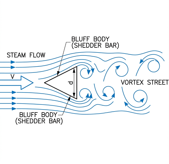
The key insight is that the frequency of vortex shedding is directly proportional to the velocity of the fluid — regardless of density, pressure, or temperature (within the operating range). This makes vortex flowmeters exceptionally stable across varying process conditions.
Vortex Meter vs. Flow Measurement: Terminology
| Term | Definition |
|---|---|
| Vortex Flow Meter | The physical instrument (sensor + electronics) |
| Vortex Flow Measurement | The technique/method of measuring flow using vortex shedding |
| Vortex Flowmeters | Alternative plural form (same meaning as vortex flow meters) |
When we refer to "vortex flow measurement," we’re emphasizing the measurement methodology — the physics and engineering approach. The "vortex flow meter" is the device that implements this methodology.
How Does Vortex Flow Measurement Work?
Understanding the working principle in detail helps engineers select the right meter and troubleshoot issues effectively.
The Strouhal Number Relationship
The fundamental equation governing vortex flow measurement is:
f = St × V / dWhere:
- f = vortex shedding frequency (Hz)
- St = Strouhal number (dimensionless, typically 0.2 for most bluff body shapes)
- V = flow velocity (m/s)
- d = characteristic width of the bluff body (m)
The Strouhal number is a dimensionless calibration constant determined experimentally for each bluff body design. For well-designed vortex meters, St remains constant over a wide range of Reynolds numbers (typically 2×10⁴ to 7×10⁶), ensuring linear measurement. For more details on fluid dynamics parameters, see Engineering ToolBox: Strouhal Number.
Learn More: For a deeper dive into the core principles, see our article How Does a Vortex Flow Meter Work: Understanding the Core Principles?
From Frequency to Flow Rate
Since flow rate Q = A × V (where A is the cross-sectional area), we can derive:
Q = f × KWhere K is the meter coefficient (or K-factor), defined as the number of pulses per unit volume (e.g., pulses/liter). This K-factor is determined during factory calibration using water and remains valid for any fluid — liquid, gas, or steam.
Sensor Technologies
Modern vortex flowmeters use one of several sensor types to detect the pressure oscillations caused by vortex shedding:
| Sensor Type | Principle | Advantages | Limitations |
|---|---|---|---|
| Piezoelectric | Pressure oscillations stress a crystal, generating voltage | Most common, wide temperature range, fast response | Sensitive to vibration |
| Capacitance | Pressure moves a diaphragm, changing capacitance | Good noise immunity | More complex electronics |
| Ultrasonic | Vortices modulate ultrasonic beam | No wetted sensor | Higher cost |
Soaring Instrument vortex meters use piezoelectric stress sensors with advanced digital signal processing to filter out pipe vibration and process noise.
Types of Vortex Flow Meters
By Installation Method
| Type | Pipe Size | Installation | Best For |
|---|---|---|---|
| Inline (Wafer/Flanged) | DN15 – DN300 | Full-bore, between flanges | Highest accuracy, smaller pipes |
| Insertion | DN80 – DN2000 | Probe inserted through ball valve | Large pipes, hot-tap installation |
Insertion-type vortex flow meters are particularly cost-effective for large line size applications (DN200+) where a full-bore meter would be prohibitively expensive.
By Electronics Configuration
| Configuration | Description | Application |
|---|---|---|
| Integrated | Sensor + transmitter in one unit | Standard installations, easy maintenance |
| Remote | Transmitter separated from sensor | High-temperature applications, better accessibility |
Soaring Instrument Product Variants
| Model | Features | Best For |
|---|---|---|
| LUGB-Z | Built-in temperature & pressure compensation, direct mass flow output | Steam, compressible gas |
| LUGB-X | LCD display, volumetric flow output | Liquid, fixed-density gas |
Steam Applications: For detailed guidance on steam flow measurement, see Why Choose Vortex Flow Meters For Steam Applications?
Vortex Flow Measurement vs. Other Technologies
How does vortex compare to alternative flow measurements technologies? Here’s an honest comparison based on our field experience:
| Feature | Vortex | Differential Pressure (Orifice) | Electromagnetic | Ultrasonic |
|---|---|---|---|---|
| Fluids | Liquid, gas, steam | Liquid, gas, steam | Conductive liquids only | Liquid (mostly) |
| Moving Parts | ❌ None | ❌ None | ❌ None | ❌ None |
| Accuracy | ±0.5% to ±1.5% | ±1% to ±2% | ±0.2% to ±0.5% | ±0.5% to ±1% |
| Turndown | 10:1 to 25:1 | 3:1 to 5:1 | 100:1+ | 50:1+ |
| Pressure Loss | Low-Medium | High | Very Low | Very Low |
| Maintenance | Minimal | Periodic (impulse lines) | Minimal | Minimal |
| Cost | Medium | Low | Medium-High | High |
When to Choose Vortex Over Differential Pressure
Vortex meters are increasingly replacing differential pressure (orifice plate) meters because:
- Wider turndown ratio — 10:1 vs. 3:1
- No impulse lines — fewer leak points and maintenance
- Direct digital output — no DP transmitter needed
- Lower permanent pressure loss — about half that of an orifice
Comparison Deep Dive: See How Do Different Flow Meter Technologies Compare in Performance and Application?
Advantages and Limitations of Vortex Flow Measurement
Advantages
Based on our field experience, here’s what the meter offers that makes it a top choice:
| Advantage | Explanation |
|---|---|
| No moving parts | Minimal wear, low maintenance, long service life (10+ years) |
| Multi-fluid capability | Same meter measures liquid, gas, and steam |
| Stable calibration | K-factor doesn’t drift over time |
| Wide Reynolds number range | Linear measurement from Re 20,000 to 7,000,000 (learn more about Reynolds number) |
| Resistant to process conditions | Unaffected by density, pressure, temperature variations (volumetric) |
| Low installation cost | Simpler than orifice plates (no impulse lines) |
Limitations
No technology is perfect. Here are the honest limitations:
| Limitation | Impact | Mitigation |
|---|---|---|
| Low-flow cutoff | Cannot measure below Re ~10,000 | Size meter correctly |
| Vibration sensitivity | Can cause false readings | Install vibration dampening, use DSP filtering |
| Straight run requirements | 10-40D upstream, 5D downstream | Use flow conditioners if space limited |
| Not for high-viscosity fluids | Poor vortex formation above ~30 cP | Use Coriolis or gear meters instead |
| Two-phase flow issues | Wet steam, entrained gas cause errors | Use separators, check steam quality |
| Cavitation risk | Liquid flow >9 m/s may cause errors | Reduce velocity, increase back-pressure |
| K-factor temperature drift | ±0.5% per 100K for stainless steel | Use integrated temperature compensation |
Expert Tips We Learned the Hard Way
Based on our field experience, here are insights competitors rarely mention:
Pipe Vibration Solutions: If you can’t eliminate vibration at the source, try rotating the meter 90° so the sensor is perpendicular to the vibration plane. Alternatively, add pipe supports on both sides of the meter.
Wet Steam Reality: Standard vortex meters only measure the vapor phase. For wet steam (quality < 95%), measurement error can exceed 5%. Consider a meter with wet steam compensation or install a steam separator upstream.
Batching Applications: Vortex meters are NOT recommended for batch processes where flow frequently drops below the low-flow cutoff. The "dribble flow" at batch end will cause significant unmeasured volume.
Noise Filter Trade-off: Increasing the noise filter setting reduces vibration sensitivity but also decreases low-flow sensitivity. Find the right balance for your application.
Troubleshooting Guide: When problems occur, consult What Is Vortex Flowmeter Troubleshooting?
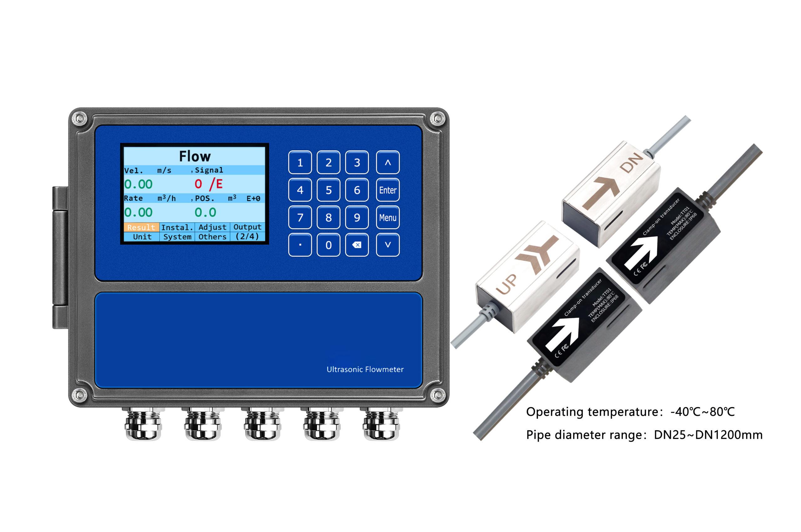
Technical Specifications: Soaring Instrument LUGB Series
All specifications are verified against our product catalog:
| Parameter | LUGB-Z (T&P Compensation) | LUGB-X (LCD Type) |
|---|---|---|
| Measuring Medium | Liquid, gas, steam | Liquid, gas, steam |
| Medium Temperature | -40°C to +250°C (optional +350°C) | -40°C to +250°C |
| Medium Pressure | 1.6 / 2.5 / 4.0 MPa | 1.6 / 2.5 / 4.0 MPa |
| Accuracy | ±1.0%, ±1.5% | ±1.0%, ±1.5% |
| Turndown Ratio | 10:1 | 10:1 |
| Velocity Range (Liquid) | 0.4 – 7 m/s | 0.4 – 7 m/s |
| Velocity Range (Gas) | 4.0 – 60 m/s | 4.0 – 60 m/s |
| Velocity Range (Steam) | 5.0 – 70 m/s | 5.0 – 70 m/s |
| Pipe Diameter (Inline) | DN15 – DN300 | DN15 – DN300 |
| Pipe Diameter (Insertion) | DN80 – DN2000 | DN80 – DN2000 |
| Body Material | 1Cr18Ni9Ti Stainless Steel | 1Cr18Ni9Ti Stainless Steel |
| Output Signal | 4-20mA, pulse, RS-485, HART | 4-20mA, pulse, RS-485 |
| Power Supply | 24V DC / 3.6V lithium battery | 24V DC / 3.6V lithium battery |
| Protection Class | IP65 | IP65 |
| Temperature Compensation | ✅ Built-in PT100 | ✅ Online compensation |
| Pressure Compensation | ✅ Built-in pressure sensor | ❌ Requires external sensor |
| Mass Flow Output | ✅ Direct kg/h | ❌ External calculation required |
Accuracy Details: For a deep dive into accuracy specifications, see What Is The Accuracy Of A Vortex Flow Meter And How Does It Compare?
Installation Best Practices
Proper installation is critical for accurate flow measurements. Based on hundreds of installations, here are the key requirements:
Straight Run Requirements
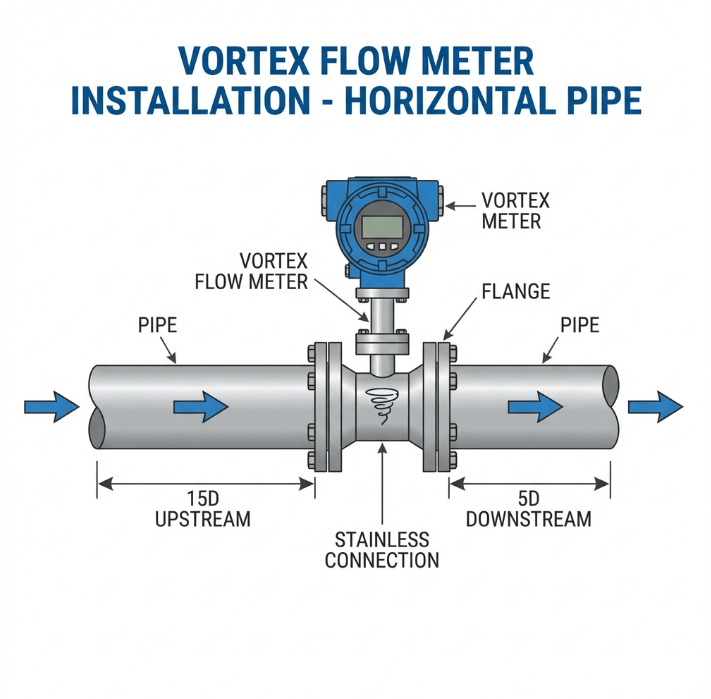
| Upstream Disturbance | Required Upstream (D = pipe diameter) | Required Downstream |
|---|---|---|
| Single elbow | 15D | 5D |
| Two elbows (same plane) | 25D | 5D |
| Two elbows (different planes) | 40D | 5D |
| Reducer/Expander | 15D | 5D |
| Fully open valve | 20D | 5D |
| Partially open valve | 50D | 5D |
Installation Details: See Vortex Flow Meter Straight Run Requirement
Lessons from the Field: Why Orientation Matters
Case Study: A chemical plant contacted us because their vortex meter was reading 15% high on a liquid line. After site inspection, we discovered the meter was installed with the sensor paddle at the bottom of a horizontal pipe — and the liquid contained entrained gas bubbles.
Root Cause: Gas bubbles accumulated at the top of the pipe, but the sensor was positioned to measure the faster-moving gas phase instead of the liquid.
Solution: Rotate the meter 90° so the sensor paddle is horizontal (perpendicular to the pipe axis).
Result: Error dropped to within ±1.5%.
Lesson: In liquid applications with potential gas entrainment, install the sensor on the side of the pipe, not the bottom.
Applications of Vortex Flow Measurement
Primary Applications
Vortex meters measure a wide range of fluids across industries:
| Application | Fluids | Industries |
|---|---|---|
| Steam Metering | Saturated, superheated steam | Power generation, chemical, food processing |
| Compressed Air | Dry air, industrial gases | Manufacturing, pneumatics |
| Natural Gas | Methane, LPG | Utilities, petrochemical |
| Cooling Water | Chilled water, condenser water | HVAC, power plants |
| Process Liquids | Solvents, chemicals, fuels | Chemical, petrochemical, pharmaceutical |
Success Story: Power Plant Steam Efficiency
A 200 MW combined-cycle power plant replaced their aging differential pressure orifice plates with Soaring Instrument LUGB-Z vortex meters on 12 steam headers.
Results after 1 year:
- 8% improvement in steam accounting accuracy
- 40% reduction in maintenance labor (no impulse line cleaning)
- $120,000 annual savings in identified steam losses
The key factor? The LUGB-Z’s temperature and pressure compensation provided accurate mass flow readings even as steam conditions fluctuated.
More Applications: See What Are the Main Applications of Vortex Flow Meters?
Frequently Asked Questions (FAQ)
What is the minimum flow rate a vortex meter can measure?
Vortex meters have a low-flow cutoff determined by the minimum Reynolds number (typically Re ~10,000) required for stable vortex shedding. Below this point, the output is clamped to zero. For water at 20°C in a DN50 pipe, this corresponds to approximately 0.5 m³/h. Always verify the minimum flow velocity specification for your specific application.
Can vortex meters measure bidirectional flow?
Standard vortex meters detect vortex frequency but not direction. However, some advanced models offer bidirectional measurement capability with specialized sensor configurations. Consult with the manufacturer if bidirectional measurement is required.
How does viscosity affect vortex flow measurement?
Viscosity affects the Reynolds number. As viscosity increases, Reynolds number decreases for the same flow rate, potentially pushing the flow below the meter’s operating range. Vortex meters are generally not recommended for fluids above 30 centipoise.
What is the typical lifespan of a vortex flow meter?
With no moving parts, vortex meters can last 15-20 years or more with minimal maintenance. The piezoelectric sensor is the primary wear item, but modern sensors are designed for 10+ years of continuous operation.
Can vortex meters measure wet steam?
Vortex meters measure the velocity of the steam phase, not the liquid droplets in wet steam. For wet steam with quality > 95%, measurement is generally acceptable. For lower-quality steam, consider integrating a wet steam compensation option or using a different technology.
Conclusion
Key Takeaways:
Vortex flow measurement uses the von Kármán effect — vortex shedding frequency is proportional to flow velocity, making it reliable across varying process conditions.
Vortex flowmeters have no moving parts, minimal maintenance, and measure liquid, gas, and steam — ideal for multi-utility facilities.
The Strouhal number relationship (f = St × V / d) provides linear measurement across a wide range of Reynolds numbers (Re 20,000 to 7,000,000).
For steam and gas applications requiring mass flow output, choose a model with integrated temperature and pressure compensation (Soaring Instrument LUGB-Z).
Proper installation — correct line size, straight run requirements, sensor orientation — is critical for accuracy.
Request a Consultation
Our engineering team has designed and supported hundreds of vortex flow measurement installations across power generation, chemical processing, and utilities. We can help with:
- Application assessment and meter sizing
- Installation design and straight run optimization
- Commissioning and calibration support
- Troubleshooting and performance optimization
Request Free Application Review | View Vortex Flow Meter Specifications
Related Articles
- How Does a Vortex Flow Meter Work: Understanding the Core Principles?
- What Is The Accuracy Of A Vortex Flow Meter And How Does It Compare?
- Why Choose Vortex Flow Meters For Steam Applications?
- What Is Vortex Flowmeter Troubleshooting?
- Vortex Flow Meter Straight Run Requirement
- What Are the Main Applications of Vortex Flow Meters?