 By Soaring Instrument Engineering Team | Updated: April 2026
When our team was commissioned to retrofit a compressed air monitoring system at a steel processing facility in 2024, we ran into a problem that countless plant engineers face: volumetric flow meters were giving wildly inconsistent readings every time ambient temperature shifted during seasonal changes. The compressors were consuming 34% more electricity than benchmarked, yet no one could pinpoint which of the 12 branch lines was leaking or overconsuming.
That project changed how we think about gas flow measurement. We replaced the aging differential pressure meters with thermal gas mass flow meters throughout the distribution network—and within six weeks, the plant manager had identified three significant leak points, trimmed compressor runtime by 22%, and saved an estimated $18,000 in annual energy costs.
The core lesson: for gas flow measurement in industrial environments, mass flow—not volumetric flow—is the number that actually matters.
Quick Answer: A thermal gas mass flow meter measures gas flow rate by detecting heat transfer from a heated sensor to the flowing gas. Because heat transfer is proportional to the number of gas molecules (mass), these meters deliver direct mass flow readings without needing external temperature or pressure correction—making them the preferred solution for compressed air systems, natural gas submetering, biogas, flare gas, and other industrial gas applications.
This guide covers everything engineers, procurement managers, and plant operators need to know: working principle, types, selection criteria, installation best practices, troubleshooting, and real-world industrial applications—all grounded in technical specifications from Soaring Instrument’s product line.
For a broader comparison of flow measurement technologies, see our guide: How Do Different Flow Meter Technologies Compare in Performance and Application?
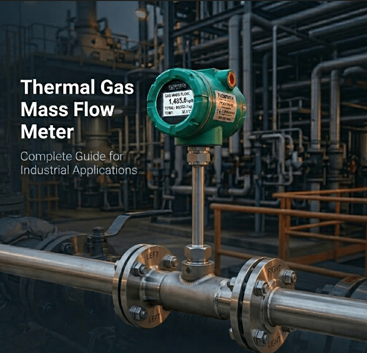
What Is a Thermal Gas Mass Flow Meter?
A thermal gas mass flow meter (also called a thermal dispersion mass flow meter or thermal mass flowmeter) is a precision instrument that measures the mass flow rate of gases directly using the principle of convective heat transfer.
Unlike volumetric flow meters—such as turbine, vortex, or differential pressure meters—thermal mass flow meters do not measure the space a gas occupies. Instead, they count “how many molecules” pass by, expressed as mass per unit time (kg/h, g/min, SCFM, Nm³/h).
Why Mass Flow Measurement Matters for Gases
Gases are compressible. The same pipeline carrying “1000 m³/h” at 20°C and 6 bar absolute carries significantly fewer molecules than 1000 m³/h at 30°C and 4 bar. A volumetric meter would report 1000 m³/h in both cases—but the actual gas delivered is completely different.
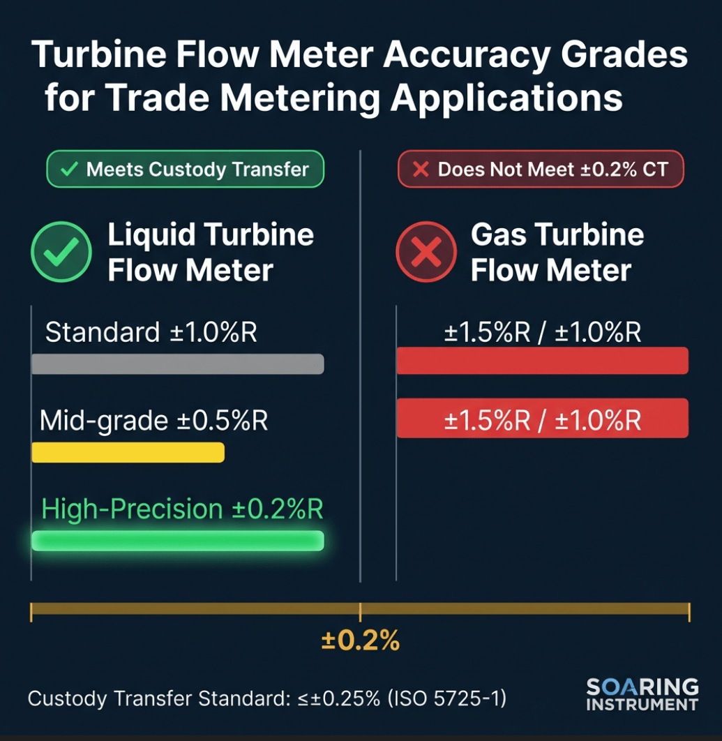
| Measurement Type | Affected by Temperature? | Affected by Pressure? | Requires Compensation? |
|---|---|---|---|
| Volumetric (m³/h) | ✅ Yes | ✅ Yes | Required |
| Mass Flow (kg/h) | ❌ No | ❌ No | Not needed |
| Std. Volume (Nm³/h) | Reference conditions only | Reference conditions only | Built-in |
This is why thermal mass flow meters are the standard for:
– Compressed air consumption monitoring
– Natural gas submetering and billing
– Biogas and landfill gas measurement
– Flare gas measurement and emissions reporting
– Combustion air control in boilers and furnaces
Related: Which Flow Meter Is Best For Natural Gas Measurement?
Thermal Mass Flow Meter Working Principle
The Core Physics: Convective Heat Transfer
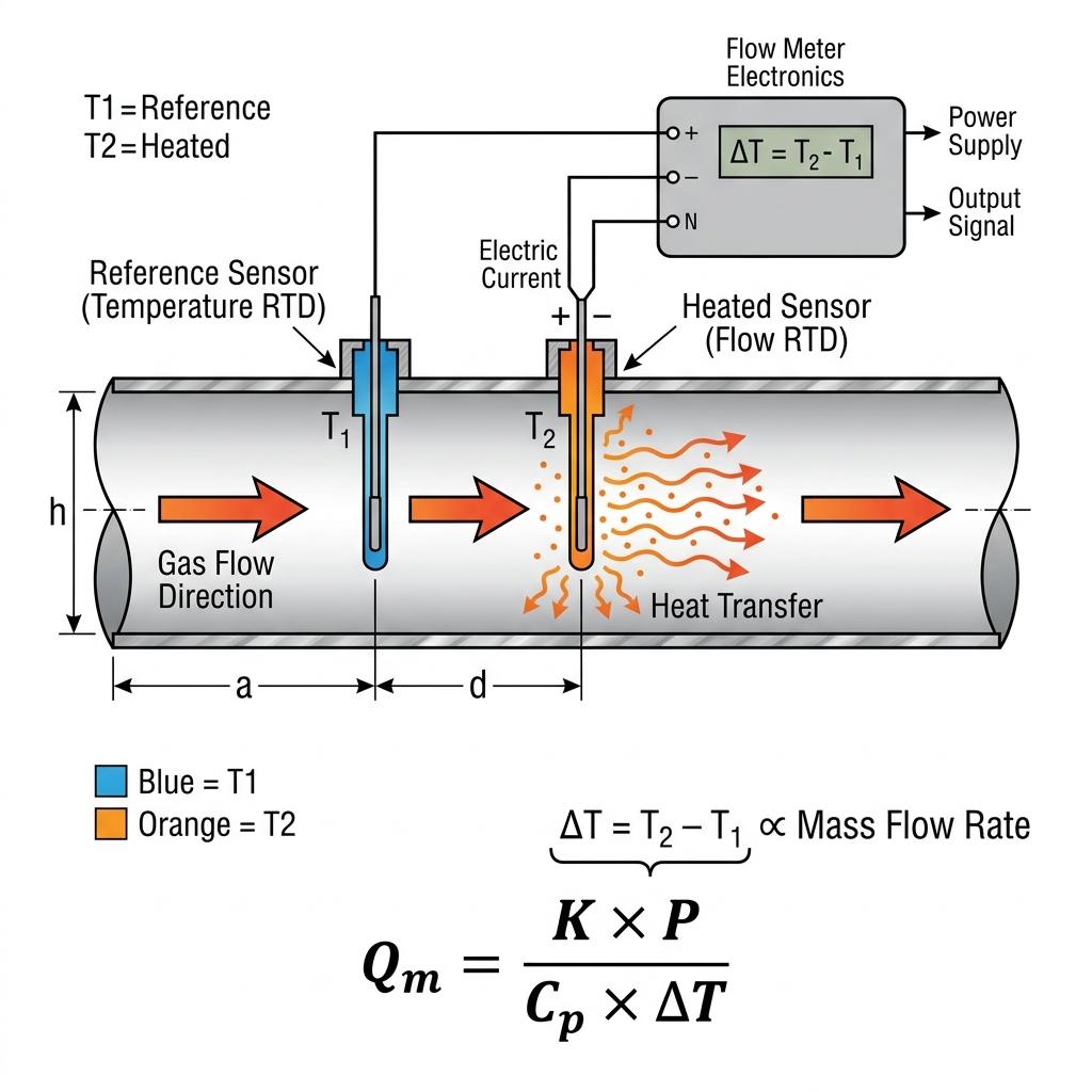
The thermal mass flow meter working principle is based on King’s Law of convective heat transfer, first described by L.V. King in 1914. The fundamental equation governing thermal flow measurement is:
$$Q_m = \frac{K \cdot P}{C_p \cdot \Delta T}$$
Where:
– Qm = Mass flow rate (kg/h or g/min)
– K = Instrument calibration constant
– P = Electrical power supplied to the heated sensor (Watts)
– Cp = Specific heat capacity of the gas (J/g·°C)
– ΔT = Temperature differential between heated sensor and reference sensor (°C)
The Two-Sensor System
Every industrial thermal gas mass flow meter contains two precision RTD (Resistance Temperature Detector) sensors housed in a protective probe:
Sensor 1: Reference RTD (Temperature Sensor)
Measures the actual gas temperature continuously. This is the “baseline.”
Sensor 2: Heated RTD (Flow Sensor)
Maintained at a constant temperature differential above the reference sensor (typically 10–40°C above gas temperature). The electrical power required to maintain this fixed overheat is the measurement signal.
The measurement logic:
– At zero flow: Minimum power needed to sustain ΔT. No molecules carry heat away.
– At low flow: Moderate power. Gas molecules gradually cool the heated sensor.
– At high flow: Maximum power. More molecules in contact with the sensor surface = greater cooling effect = more energy needed.
The result: electrical power ∝ mass flow rate. No pressure transducer, no temperature transmitter, no flow computer—the three-variables-into-one calculation happens inside the meter.
Constant Temperature Differential vs. Constant Power Methods
Two design approaches exist for industrial thermal meters:
| Method | How It Works | Advantages | Disadvantages |
|---|---|---|---|
| Constant ΔT (CT) | Power varies to maintain fixed ΔT | Fast response, wide turndown, best for fluctuating flow | Slightly higher sensor temperature in low-flow |
| Constant Power (CP) | Power is fixed, ΔT is measured | Simpler circuit, lower cost | Slower response, narrower dynamic range |
Our recommendation: For most industrial gas applications—especially compressed air systems with highly variable load profiles—Constant Temperature Differential (CT) thermal meters offer superior performance. All Soaring Instrument thermal gas meters use the CT method.
How Thermal Meters Differ from Hot Wire Anemometers
Engineers sometimes confuse thermal mass flow meters with hot wire anemometers. Key distinctions:
- Anemometers: Measure velocity at a single point using a fragile bare wire (0.004mm diameter). Suitable for laboratory or clean-room conditions only.
- Industrial Thermal Mass Meters: Use robust RTD probes in stainless steel sheaths, calibrated for specific gases, and output mass flow (not velocity). Designed for 24/7 industrial operation with no maintenance.
Types of Thermal Gas Mass Flow Meters
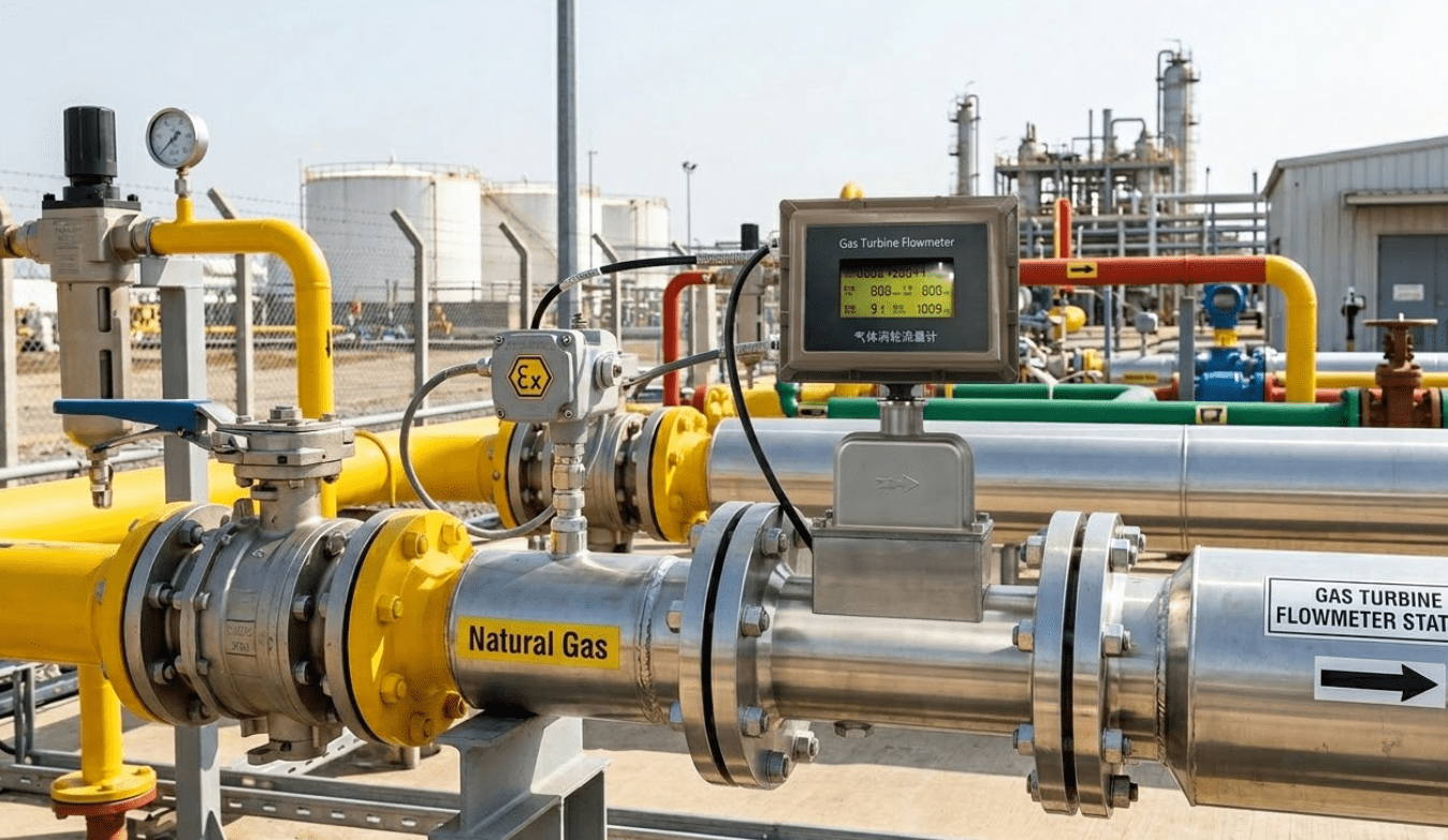
1. Insertion (Probe) Type — Most Common in Industry
The probe is inserted into the pipe through a compression fitting, hot-tap assembly, or ball valve. The sensors sit at a specific depth from the pipe wall (typically at the hydraulic center of the pipe).
Soaring Instrument Plug-in Pipe Type specifications:
– Pipe Diameter: DN40 and above
– Velocity Range: 0.1–120 Nm/s
– Accuracy: ±1.0%, ±1.5%
– Turndown Ratio: 100:1
– Power Supply: 24VDC / 220VAC
– Protection: IP65
– Explosion-Proof: Exd II CT4
– Output: 4-20mA, RS-485/HART, pulse/frequency
Best for: Large pipes (DN50+), retrofits on existing pipelines, applications where pipe cutting is impractical.
Field insight: On the steel plant project mentioned above, our team installed 11 insertion-type meters via hot tap without shutting down production for a single day. The ball valve assembly allows the probe to be retracted for maintenance while the line stays pressurized—a significant operational advantage.
2. Inline (Pipeline / In-line) Type
The meter is manufactured as a complete flow spool that is flanged into the pipeline. Sensors are integrated inside the flow body.
Soaring Instrument Pipeline Type specifications:
– Applicable Media: Moisture-free gas (except acetylene)
– Accuracy: ±1.0%, ±1.5%
– Turndown Ratio: 100:1
– Temperature: Ambient -20 to +50°C; Medium -20 to +120°C
– Work Pressure: 2.5 MPa, 4.0 MPa
– Output: RS-485/HART; 4-20mA; pulse/frequency
– Pipe Diameter: DN10–DN300
– Display: Four-line LCD display
– Alarm: Relay dry contact output, up to two channels
Best for: Small to medium pipes (DN10–DN100), new installations, critical measurement points where accuracy is paramount, and applications requiring ATEX/explosion-proof certification.
3. Bypass / Capillary Type (Industry Background — Not a Soaring Instrument Product)
Note: This type is included for industry context only. Soaring Instrument’s thermal gas mass flow meter product line covers Plug-in Pipe (Insertion) and Pipeline (Inline) types as described above.
A bypass tube with laminar flow elements diverts a small, proportional fraction of the main flow. Sensors measure the bypassed fraction and calculate total flow. This design is common in laboratory instruments and semiconductor process gas measurement.
Best for: Very low flow rates (mL/min to L/min), research labs, semi-conductor fabrication.
Limitation: The capillary tube is susceptible to clogging by particulates. Not recommended for industrial process gas without upstream filtration.
Type Comparison Summary
| Parameter | Insertion Type | Inline Type | Bypass/Capillary |
|---|---|---|---|
| Pipe Size | DN40–DN3000+ | DN10–DN300 | DN3–DN50 |
| Flow Range | Medium–High | Low–Medium | Ultra-low |
| Installation | Minimal disruption | Requires pipe spool | Requires pipe spool |
| Maintenance | Hot-tap retraction | Flow body replacement | Periodic filter clean |
| Cost | Lower | Medium | Higher (small pipes) |
| Best Application | Industrial gas, compressed air | Process control | Lab, semiconductor |
Key Technical Advantages: Why Choose Thermal Over Other Technologies?
Having specified flow meters for gas applications across over 200 industrial projects, our engineering team has developed clear guidelines on when thermal technology outperforms alternatives.
Advantage 1: True Mass Flow — No PT Compensation Needed
This is the single most important differentiator. When you need to:
– Calculate combustion stoichiometry
– Bill compressed air in Nm³ (not actual m³)
– Report greenhouse gas emissions in kg
– Control reagent gas injection by mass
…you need mass flow. Thermal meters deliver it directly. Vortex, turbine, and differential pressure meters deliver volumetric flow—and require dedicated temperature and pressure transmitters plus a multi-variable flow computer to convert to mass or standard conditions. That’s additional cost, additional failure points, and additional calibration burden.
Advantage 2: Exceptional Turndown Ratio (100:1 standard)
Soaring Instrument thermal gas mass flow meters offer a 100:1 turndown ratio—meaning a single meter calibrated for 1000 Nm³/h can still accurately measure as low as 10 Nm³/h.
This is critical for:
– Compressed air systems where nighttime/weekend flow drops to 2–5% of daytime peak
– Biogas digesters where production varies seasonally
– Natural gas submetering where building demand fluctuates with occupancy
In contrast:
– Vortex meters: typically 10:1–30:1
– Turbine meters: typically 10:1–30:1
– Differential pressure (orifice plate): typically 3:1–5:1
Advantage 3: Low Velocity Detection — Leak and Minimum-Flow Applications
Soaring Instrument’s thermal meters can detect gas velocity as low as 0.05 m/s (per product feature specifications). This capability is virtually unmatched by other industrial flow measurement technologies.
Practical application: In large compressed air distribution systems, leaks often cause flows of just 0.3–2.0 m/s in branch lines overnight when production is stopped. A vortex meter (minimum velocity: 4.0 m/s for gas) simply cannot detect this. A thermal meter can—and quantify it precisely.
We’ve measured leaks as small as 0.8 Nm³/h in a DN100 branch line, which corresponded to a 3mm orifice leak costing the client approximately €3,200/year in wasted compression energy.
Advantage 4: No Moving Parts = Maximum Reliability
Unlike turbine or positive displacement meters, thermal gas mass flow meters have no mechanical moving parts. This means:
- Zero mechanical wear
- No risk of bearing failure or rotor seizure
- No calibration drift from physical component changes
- Suitable for continuous 24/7 operation without scheduled maintenance
- Viable in pulsating flow conditions (e.g., downstream of reciprocating compressors) where turbine meters suffer premature bearing failure
Related: Why Choose Turbine Flow Meters for Industrial Applications? — a comparison that covers when turbine technology is and isn’t the right choice
Advantage 5: Wide Gas Compatibility
A single thermal meter design can be calibrated for virtually any single-component gas or stable gas mixture:
– Compressed air
– Natural gas (pipeline quality)
– Nitrogen (N₂)
– Biogas (calibrated for specific CH₄/CO₂ mix)
– Hydrogen (H₂)
– Carbon dioxide (CO₂)
– Argon (Ar)
– Flue gas and combustion products
Important limitation: Thermal meters are calibrated for a specific gas or gas mixture. If gas composition changes significantly during operation (e.g., variable biogas methane content), measurement accuracy will be affected. Factor this into your selection process and request factory calibration for your exact gas composition.
Selection Guide: How to Choose the Right Thermal Gas Mass Flow Meter
Step 1: Define Your Gas Composition
Identify the gas to be measured. For natural gas, specify methane content. For biogas, specify typical CH₄/CO₂ ratio. For compressed air, standard air calibration applies.
Rule: Never use an air-calibrated meter for natural gas without conversion or recalibration.
Step 2: Calculate Flow Range and Pipe Size
Determine minimum and maximum expected flow rates. Calculate the corresponding velocity in your pipe:
$$v = \frac{Q}{\pi \times (D/2)^2 \times 3600}$$
Where v = velocity (m/s), Q = volumetric flow (m³/h), D = pipe internal diameter (m).
Velocity guidelines for Soaring Instrument thermal meters:
– Minimum measurable velocity: 0.05 m/s (per product feature specification)
– Maximum measurable velocity: 120 Nm/s
– Rated velocity range (technical parameter): 0.1–120 Nm/s
– Optimal accuracy range: 2–80 Nm/s
Step 3: Evaluate Process Conditions
| Condition | Requirement | Soaring Instrument Spec |
|---|---|---|
| Gas temperature | Must be within operating range | Medium: -20°C to +120°C |
| Ambient temperature | Must be within operating range | -20°C to +50°C |
| Line pressure | Must not exceed rating | 2.5 MPa or 4.0 MPa |
| Gas humidity | Prefer dry or slightly humid gas | Moisture-free gas recommended |
| Particle content | Pipe should be clean | Upstream filter recommended if dusty |
| Pipe diameter | Determines meter type | DN10–DN600+ |
Step 4: Determine Installation Requirements
For insertion type meters:
– Minimum straight pipe upstream: 10–15D (D = pipe diameter)
– Minimum straight pipe downstream: 5D
– Insertion depth: typically to pipe centerline
– Access fitting: ball valve or compression fitting
For inline type meters:
– Same upstream/downstream straight run requirements
– Process connection: flange or threaded (DN ≤ 50)
– Must be installed in accessible location for calibration access
See our detailed guide: What Are The Critical Straight Run Requirements For Different Flow Meters?
Step 5: Output and Communication Requirements
| Application | Recommended Output |
|---|---|
| DCS/PLC integration | 4-20mA + RS-485 (Modbus) |
| Energy management system | 4-20mA + pulse (for totalization) |
| HART-enabled control system | HART protocol |
| Simple panel display | 4-20mA to panel indicator |
| Wireless/IoT gateway | RS-485 + data concentrator |
Industrial Applications: Where Thermal Gas Mass Flow Meters Excel
Application 1: Compressed Air Flow Measurement
This is the most widespread industrial application for thermal gas mass flow meters worldwide—and for good reason.
The problem with compressed air:
According to the U.S. Department of Energy, compressed air systems account for 10–30% of industrial electricity consumption. Studies consistently show that 25–40% of compressed air produced is wasted through leaks in typical industrial plants.
Why thermal meters are ideal:
– Direct Nm³/h measurement—the unit compressed air is actually billed and optimized in
– Low-velocity detection catches overnight/weekend leaks when production is idle
– Wide turndown accommodates huge demand swings between shift peak and off-peak
– Insertion installation means no production downtime for installation
ROI case study: At the steel processing facility we described in the introduction, 11 insertion-type thermal meters were installed across the compressed air distribution network. Total investment: approximately $4,200 in hardware. Annual energy savings identified and captured: $18,000. Payback period: under 3 months.
For a technology comparison specifically for compressed air: Why Choose Vortex Flow Meters For Compressed Air Measurement? — this covers scenarios where vortex technology may be preferred
Application 2: Natural Gas Measurement to Combustion Sources
Boilers, furnaces, kilns, and burner systems consume natural gas. Measuring flow to individual combustion sources allows:
– Calculation of combustion efficiency (air-to-fuel ratio optimization)
– Cost allocation between production departments
– Detection of burner degradation (flow increase for same heat output)
– Compliance with emissions regulations (fuel consumption × emission factor)
Selection note: For natural gas measurement, specify the gas composition at ordering time. Soaring Instrument thermal meters can be calibrated for natural gas with specified heating value.
Application 3: Biogas and Landfill Gas Monitoring
Biogas typically contains 50–70% methane (CH₄) and 30–50% CO₂, with trace amounts of H₂S and moisture. Accurate flow measurement is required for:
– Biogas-to-energy conversion optimization
– Carbon credit verification (regulatory agencies require mass flow data)
– Flare operation monitoring
– Feed rate control to gas engines or boilers
Special consideration: Biogas methane content varies with feedstock composition and temperature. Request calibration for your average methane percentage and verify measurement error sensitivity to composition variation. For highly variable compositions (>±10% CH₄ variation), consider a methane fraction analyzer input to the flow meter.
Application 4: Boiler Combustion Air Measurement
Optimizing the air-to-fuel ratio in large industrial boilers is one of the highest-impact energy efficiency interventions available. Thermal gas mass flow meters installed on the combustion air duct can:
– Enable real-time stoichiometric control
– Reduce excess air (common sources of boiler inefficiency)
– Detect air infiltration (negative pressure boilers)
– Monitor secondary air distribution in multi-zone burners
Measurement environment note: Combustion air applications involve elevated temperatures and potentially dusty conditions. Specify stainless steel probes with IP65 or higher protection.
Application 5: Plant Air Leak Detection and Submetering
Installing thermal meters at each building, production line, or major equipment group creates a “virtual metering” network that can:
– Identify which areas consume the most compressed air
– Detect leaks by comparing supply and delivery totals
– Enable energy cost allocation to departments
– Support ISO 50001 energy management certification
Our recommended architecture: One master meter on the compressor discharge header + branch meters on each major circuit. This “top-down” approach lets you perform leak audits by subtraction: compressor output minus all branch meter totals = system leakage.
Application 6: Wastewater Treatment Aeration Air
Biological wastewater treatment plants use aeration blowers to supply oxygen to the activated sludge process. Aeration air accounts for 50–70% of a WWTP’s electricity consumption. Precise air flow measurement enables:
– DO (dissolved oxygen) control optimization
– Blower efficiency monitoring
– Energy benchmarking (kWh per m³ treated)
Thermal insertion meters are ideal here: they handle the large pipe diameters (DN200–DN600) typical of aeration system headers, can be retracted without process shutdown, and readily tolerate the humidity and temperature swings in blower discharge air.
Related: Why Accurate Flow Measurement is Critical for Wastewater Treatment Plants?
Application 7: Flue Gas and Emissions Monitoring
Stack flow measurement for emissions compliance is a specialized application. Thermal meters are used when:
– Stack gas temperature is within meter range (-20 to +120°C, standard; higher temperatures require special versions)
– Gas composition is known and relatively stable
– No moisture condensation is present
Warning: In stacks where gas temperature drops below the dew point, condensation on the sensor causes serious measurement errors and potential corrosion. Ensure probe material compatibility and install upstream of any cooling section.
Installation Best Practices
Upstream Straight Run Requirements
Flow profile distortion is the primary source of installation error. The thermal mass flow working principle relies on a fully developed turbulent flow profile at the measurement point.
| Upstream Obstruction | Required Straight Run (pipe diameters) |
|---|---|
| Single 90° elbow | 10D–15D |
| Two 90° elbows (same plane) | 15D–20D |
| Two 90° elbows (different planes) | 20D–25D |
| Fully open gate valve | 5D |
| Control valve or partially open valve | 20D–30D |
| Reducer (pipe contraction) | 10D–15D |
| Expander (pipe expansion) | 20D–25D |
Downstream requirement: Minimum 5D after the meter.
When insufficient straight run exists: Flow conditioning plates or multi-point averaging probes can reduce straight run requirements to as little as 3–5D upstream. Consult Soaring Instrument application engineers for site-specific guidance.
Probe Insertion Depth
For insertion type meters in single-point measurement mode:
– Insert to pipe centerline for pipes DN50–DN200
– For larger pipes (DN200+), specific insertion depth may differ—follow manufacturer’s calibration documentation
Field tip: During our plant installations, we use a simple depth gauge rod to confirm probe tip position before tightening the compression fitting. A 2cm insertion error in a DN100 pipe shifts the measurement point enough to introduce 3–5% systematic error. Take the 90 seconds to verify—it’s worth it.
Orientation and Mounting Position
Thermal meters can be installed in horizontal, vertical, or inclined pipes. For wet gas applications (near saturation), prefer mounting with the probe at the top of a horizontal pipe so condensed liquid drains away from the sensor.
Avoid: Installing in low points of horizontal runs where liquid may pool and submerge the sensor.
Grounding and Electrical Installation
- Use shielded cable for 4-20mA signal wiring; ground the shield at the transmitter end only
- Maintain at least 30cm separation from high-voltage power cables
- Follow local electrical codes for explosion-proof applications (Exd II CT4)
- Verify 24VDC supply voltage at the meter terminals (not just at the power supply output)—cable voltage drop matters in long runs
See also: What Are the Key Requirements for Flow Meter Installation?
Troubleshooting Common Issues
| Symptom | Probable Cause | Diagnostic Check | Solution |
|---|---|---|---|
| Reading stuck at zero | Probe not reaching gas stream | Check insertion depth | Adjust probe depth to pipe center |
| Reading too high vs. reference | Insufficient upstream straight run | Verify installation distance | Add flow conditioning or relocate |
| Reading too low vs. reference | Sensor fouling / contamination | Inspect sensor surface | Clean with dry compressed air; avoid solvents |
| Unstable/fluctuating reading | Pulsating flow from reciprocating compressor | Install dampening volume upstream | Add surge tank or use averaging probe |
| Reading drifts over time | Gas composition change | Verify gas composition | Recalibrate for actual gas |
| No output signal (4-20mA = 0V) | Power supply failure or wiring fault | Check supply voltage at meter terminals | Verify 24VDC ±15% at meter; check fuse |
| Condensation on sensor | Gas temperature below dew point | Check gas temperature and pressure | Relocate upstream; add heat tracing |
| Alarm output active | Flow exceeds upper limit, or out-of-range | Check actual flow vs. configured range | Adjust alarm setpoints |
Lessons from the Field: The “Ghost Flow” Problem
One of the most frustrating troubleshooting calls we’ve received was from a chemical plant reporting “ghost flows”—their thermal meter was showing 15–30 Nm³/h in a supposedly closed nitrogen purge line.
After a site visit, our field engineer identified the cause: a leaking isolation valve two meters upstream was allowing regulated instrument air to back-flow into the nitrogen line, creating a real (but unintended) flow that the meter was correctly measuring. The plant had a process integrity issue, not an instrumentation problem.
Lesson: Before condemning a thermal meter for an unexpected reading, verify that the reading is actually wrong. Thermal meters don’t generate phantom readings—if they show flow, there is flow (or thermal convection from a large thermal gradient). The interesting question is where it’s coming from.
Technical Specifications: Soaring Instrument Thermal Gas Mass Flow Meter
Important: All specifications below are obtained directly from Soaring Instrument’s official product catalog. Do not use specifications from third-party sources for procurement decisions.
Plug-in Pipe Type (Insertion Type)
| Parameter | Specification |
|---|---|
| Applicable Media | Moisture-free gas (except acetylene gas) |
| Accuracy | ±1.0%, ±1.5% |
| Temperature — Ambient | -20°C to +50°C |
| Temperature — Medium | -20°C to +120°C |
| Power Supply | 24VDC / 220VAC |
| Working Pressure | 2.5 MPa, 4.0 MPa |
| Response Time | ≤1 second |
| Output | RS-485/HART; 4-20mA analog; pulse/frequency |
| Pipe Diameter | DN40 and above |
| Velocity Range | 0.1–120 Nm/s |
| Turndown Ratio | 100:1 |
| Explosion-Proof | Exd II CT4 |
| Protection Class | IP65 |
| Alarm | Relay dry contact, up to 2 channels |
| Process Connection | Ball valve / flange (customizable) |
| Electrical Interface | M20×1.5 |
| Display | Four-line LCD |
Pipeline (Inline) Type
| Parameter | Specification |
|---|---|
| Applicable Media | Moisture-free gas (except acetylene gas) |
| Accuracy | ±1.0%, ±1.5% |
| Temperature — Ambient | -20°C to +50°C |
| Temperature — Medium | -20°C to +120°C |
| Power Supply | 24VDC / 220VAC |
| Working Pressure | 2.5 MPa, 4.0 MPa |
| Response Time | ≤1 second |
| Output | RS-485/HART; 4-20mA analog; pulse/frequency |
| Pipe Diameter | DN10–DN300 |
| Velocity Range | 0.1–120 Nm/s |
| Turndown Ratio | 100:1 |
| Explosion-Proof | Exd II CT4 |
| Protection Class | IP65 |
| Alarm | Relay dry contact, up to 2 channels |
| Process Connection | Flange / threaded |
Technology Comparison: Thermal vs. Other Gas Flow Meters
| Parameter | Thermal Mass | Vortex | Turbine (Gas) | Differential Pressure |
|---|---|---|---|---|
| Measures mass directly? | ✅ Yes | ❌ No | ❌ No | ❌ No |
| PT compensation needed? | ❌ No | ✅ Required | ✅ Required | ✅ Required |
| Typical accuracy | ±1%–1.5% | ±1%–1.5% | ±1%–1.5% | ±1%–3% (incl. PT) |
| Turndown ratio | 100:1 | 10:1–30:1 | 10:1–30:1 | 3:1–10:1 |
| Moving parts | None | None (bluff body) | Yes (rotor/bearings) | None (orifice/venturi) |
| Min. detectable velocity | 0.05 m/s | 4 m/s | 1 m/s | ~0.5 m/s |
| Pressure drop | Very low | Medium | Low–Medium | High (orifice plate) |
| Suitable for wet gas? | Limited | Yes (vortex) | Limited | Yes |
| Best for large pipes? | ✅ (insertion type) | ✅ (insertion vortex) | ✅ | Moderate |
For steam applications specifically, vortex meters remain the dominant technology. See: Steam Flow Meter: Types, Selection & Best Practices
FAQ: Thermal Gas Mass Flow Meters
Q1: Do thermal mass flow meters need temperature and pressure compensation?
No. This is the defining advantage of thermal mass flow technology. The measurement is directly based on heat transfer (which is intrinsically a mass-dependent phenomenon), so the result is already in mass flow units (kg/h, g/min) or standard volume (Nm³/h at specified reference conditions). You do not need separate T or P transmitters for the primary flow measurement.
However, if you want to calculate process volumetric flow at actual conditions (ACFM/m³/h at operating P and T), you would need to apply a correction using operating temperature and pressure. Most meter displays and outputs can be configured to provide either standard or actual volumetric flow.
Q2: Can thermal mass flow meters measure wet or saturated gas?
With caution. Moisture in vapor phase generally has a minor effect on thermal readings. However, condensation (liquid droplets on the sensor surface) causes serious problems: the liquid’s very high heat capacity creates a large false reading, and corrosion is possible.
Best practices for potentially wet gas:
– Mount sensor at the top of horizontal pipes
– Maintain gas temperature above dew point at the measurement point
– Consider heat tracing in cold climates
– Use a knockout pot upstream to remove entrained liquid
– For consistently wet gas, consider a vortex or ultrasonic flow meter instead
Q3: What is the difference between insertion type and inline type thermal meters?
Insertion type: A probe is inserted through a fitting into an existing pipe. The sensing elements are positioned at the tip of the probe, typically at the pipe centerline. Best for large pipes (DN50+) and retrofit applications. Easy to install without cutting pipe.
Inline type: A complete flow body is flanged into the pipeline. The flow path and sensing elements are integrated. Best for small-to-medium pipes (DN10–DN300) and new installations where highest accuracy is required.
For a practical rule: pipes DN50 and smaller generally use inline type; DN80+ use insertion type; DN50–DN100 can go either way depending on accuracy requirements and installation constraints.
Q4: How often do thermal gas mass flow meters need calibration?
Unlike some flow meter technologies, thermal mass flow meters do not require annual factory recalibration under most industrial conditions—provided:
– Gas composition has not changed significantly
– No visible physical damage or fouling has occurred
– The meter continuously shows plausible readings with no alarm flags
In practice, we recommend a verification check every 12–24 months using a portable reference instrument (such as a clamp-on ultrasonic meter or a calibrated reference meter in parallel). If readings agree within ±2%, the meter is performing correctly.
Related: What Do You Need to Know About Flow Meter Calibration?
Q5: Can one thermal meter be used for multiple gases?
Not without recalibration. Each gas has different thermal properties (specific heat Cp, thermal conductivity λ, density ρ). A meter calibrated for air will over-read or under-read for natural gas or nitrogen.
Some advanced multi-gas thermal meters include selectable calibration curves for several gases—but they must have been factory-calibrated for each specific gas stored in the curve library. Consult your meter’s documentation before switching gases on site.
Q6: What’s the minimum pipe size for thermal gas mass flow measurement?
Soaring Instrument’s inline type thermal meters are available from DN10 (approximately 3/8 inch). For very small pipes or tubes (below DN10), laboratory-grade thermal mass flow controllers are typically used.
For insertion type meters, the minimum practical pipe size is approximately DN40 (due to probe dimensions and insertion depth requirements).
Q7: Are thermal gas mass flow meters suitable for explosive gas atmospheres?
Yes, with appropriate certification. Soaring Instrument thermal gas mass flow meters carry Exd II CT4 explosion-proof certification, meeting the requirements for Zone 1 and Zone 2 hazardous area classifications under ATEX and IECEx standards. This makes them suitable for:
– Natural gas pipelines and distribution
– Hydrogen measurement in fuel cell or petrochemical applications (with appropriate zone classification verification)
– Biogas plants
– Solvent vapor environments
However, the safety case must be specifically evaluated for hydrogen service due to hydrogen’s unique ignition properties—consult a qualified ATEX engineer.
Conclusion: Key Takeaways
Thermal gas mass flow meters directly measure mass flow using convective heat transfer—no temperature or pressure compensation needed. This makes them uniquely suitable for gases where volumetric readings are unreliable.
The 100:1 turndown ratio makes thermal meters ideal for systems with variable demand: compressed air networks, boiler fuel lines, biogas systems.
Low-velocity detection capability (as low as 0.05 m/s per Soaring Instrument product specification) makes thermal meters the go-to technology for leak detection and low-flow applications that other technologies simply cannot address.
No moving parts means minimal maintenance, high reliability, and long service life in 24/7 industrial operation.
Calibration is gas-specific. Always specify gas composition at the time of ordering and verify calibration if gas composition changes.
Installation quality dominates measurement quality. Insufficient upstream straight run is the #1 cause of systematic thermal meter errors in the field. Invest in proper installation from the start.
Get Expert Advice on Your Application
At Soaring Instrument, our engineering team has supported thermal mass flow measurement projects across steel, chemical, pharmaceutical, food & beverage, wastewater, and oil & gas industries. We manufacture both insertion-type and inline thermal gas mass flow meters, calibrated for your specific gas and application conditions.
Ready to discuss your project?
📧 Contact our application engineers — typically respond within 24 hours
🌐 Product page: https://soaringinstrument.com/
📞 Phone: +86-21-57652429
Related Articles
- How Do Different Flow Meter Technologies Compare in Performance and Application?
- Why Choose Vortex Flow Meters For Compressed Air Measurement?
- Which Flow Meter Is Best For Natural Gas Measurement?
- Steam Flow Meter: Types, Selection & Best Practices
- What Are The Critical Straight Run Requirements For Different Flow Meters?
- What Do You Need to Know About Flow Meter Calibration?
- Why Accurate Flow Measurement is Critical for Wastewater Treatment Plants?
- How Do Different Types of Flow Meters Work?
© 2026 Shanghai Soaring Instrument Technology Co., Ltd. | soaringinstrument.com | All product specifications sourced from Soaring Instrument official product catalog.