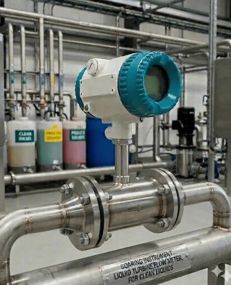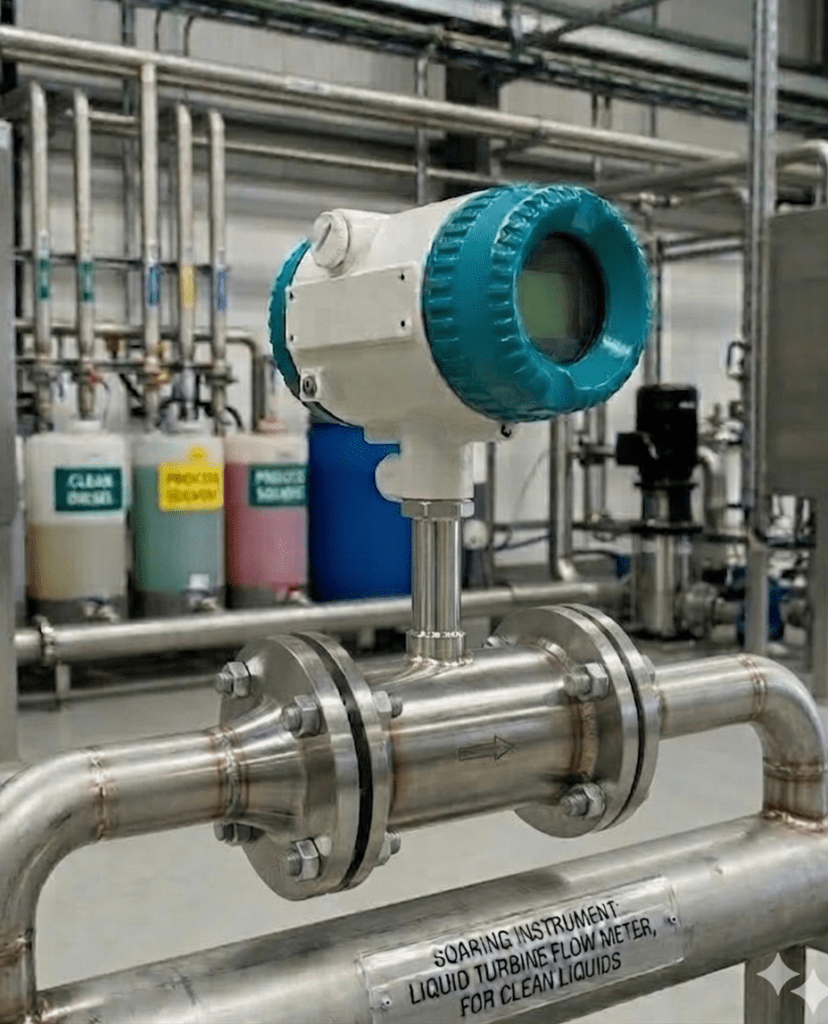
You’ve been asked to measure fuel consumption in a blending line. The fluid is clean diesel, the flow rate is 8 m³/h, and the purchasing team wants ±0.5% accuracy. You open your browser and find page after page of product listings—but no one explains how to actually select the right liquid turbine flow meter for your conditions. Sound familiar?
This guide fills that gap. Based on real application data and Soaring Instrument’s technical specifications, we’ll walk you through every selection variable—viscosity limits, flow range sizing, connection types, accuracy classes, and installation rules—so you leave with a confident, documented decision.
Quick Answer: A liquid turbine flow meter is ideal for clean, low-viscosity liquids (kinematic viscosity ≤5×10⁻⁶ m²/s) where you need high accuracy (±0.5%R standard, ±0.2%R custom) and pulse output for totalization or custody transfer. It is not suitable for slurries, dirty fluids, or highly viscous media without special calibration.
👉 For a comparison with other flow meter types for clean liquids, see: How Do Turbine and Electromagnetic Flow Meters Compare?
What Is a Liquid Turbine Flow Meter?
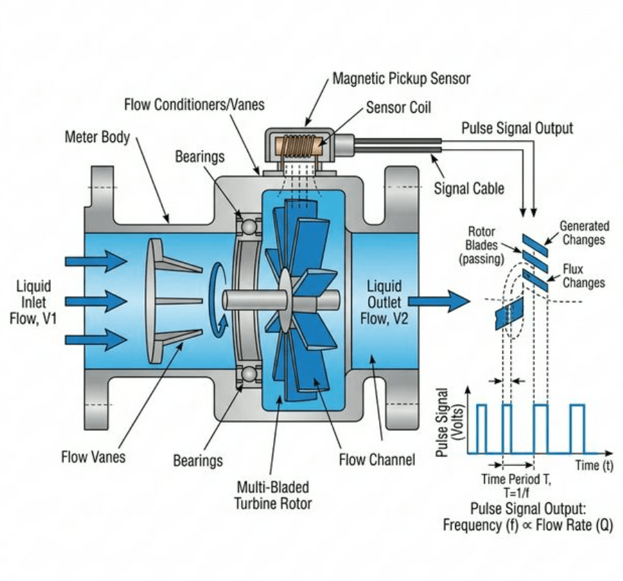
A liquid turbine flow meter is a velocity-type volumetric flow meter. Inside a machined flow body, a multi-bladed rotor (turbine) is mounted on precision bearings and positioned axially in the flow stream. As the liquid passes through, it imparts kinetic energy to the rotor blades, spinning the rotor at a speed directly proportional to the volumetric flow rate.
A magnetic or Hall-effect pickup sensor mounted on the meter body detects each rotor blade as it passes, generating a pulse. The total pulse count equals the total volume; the pulse frequency equals the instantaneous flow rate. This principle is defined by the K-factor (pulses per unit volume), a fixed calibration constant for each meter.
👉 Deep dive: Turbine Flow Meter Working Principle: How Does It Operate?
Key Differentiators vs. Other Flow Meter Types
| Feature | Liquid Turbine Flow Meter | Electromagnetic Flow Meter | Vortex Flow Meter | Ultrasonic Flow Meter |
|---|---|---|---|---|
| Fluid requirement | Clean, low-viscosity liquid | Conductive liquid (≥20 μS/cm) | Low-viscosity liquid or gas | Any liquid (clamp-on or inline) |
| Accuracy | ±0.5%R (±0.2%R custom) | ±0.5% / ±0.2% custom | ±1.0%–1.5% | ±1.0% |
| Moving parts | Yes (rotor + bearings) | No | No | No |
| Pressure loss | Low-moderate | None | Low | None |
| Viscosity limit | ≤5×10⁻⁶ m²/s standard | Not limited by viscosity | Low viscosity preferred | Not greatly affected |
| Best for | Trade settlement, batching | Conductive liquids, slurry | Steam, gas, clean liquid | Non-invasive, large pipes |
| Cost | Low–moderate | Moderate | Moderate | Moderate–high |
How to Select the Right Liquid Turbine Flow Meter: 6 Key Parameters
Selection is not guesswork. Each variable below narrows your specification until only one meter configuration fits. Work through them in order.
Parameter 1: Fluid Compatibility (The First Gate)
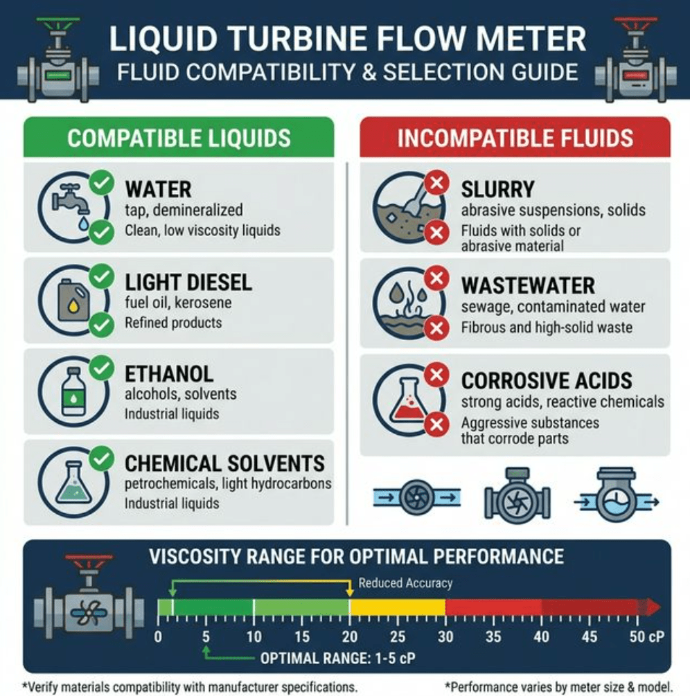
Liquid turbine flow meters are designed specifically for clean liquids. Per Soaring Instrument product documentation (JB/T 9246-1999), the fluid must meet all three criteria:
- No fibers or large particles — fibrous media will jam the rotor; particles above 75 μm require an upstream Y-strainer (installed ≥20 pipe diameters upstream).
- No ferromagnetic impurities — iron particles interfere with the magnetic pickup signal. If iron contamination is possible, use a Hall-effect pickup instead of a reluctance pickup.
- Kinematic viscosity ≤5×10⁻⁶ m²/s at working temperature — this is the standard operating limit. For liquids with kinematic viscosity greater than 5×10⁻⁶ m²/s, the meter can still be used after real-liquid calibration at your actual operating conditions.
Common Compatible Liquids (Clean Applications)
| Liquid Type | Typical Viscosity (cP) | Compatible? | Special Note |
|---|---|---|---|
| Water (20°C) | ~1.0 cP | ✅ Yes | Ensure no iron particles |
| Light diesel / Fuel oil | 2–6 cP | ✅ Yes | Preferred for custody transfer |
| Ethanol / Methanol (industrial) | ~1–2 cP | ✅ Yes | Verify material compatibility |
| Chemical solvents (low-visc.) | 0.5–5 cP | ✅ Yes | Check 304/316 SS compatibility |
| Hydraulic oil (ISO VG 32) | ~30 cP at 40°C | ⚠️ Calibration required | Perform real-liquid calibration |
| Glycol solution >50% | ~15–50 cP | ⚠️ Calibration required | Reduced linearity range |
| Wastewater / Slurry | Variable | ❌ No | Use electromagnetic flow meter |
| Corrosive acids / Alkalis | Variable | ❌ No (standard) | Consider clamp-on ultrasonic |
👉 For corrosive or aggressive liquids: Flow Meter for Corrosive Liquids: Why Clamp-On Wins
Parameter 2: Flow Range Sizing (60%–75% Rule)
This is the most commonly misapplied sizing rule. Turbine meter manufacturers—including independent analysis from All About Circuits and industry references—consistently recommend sizing so your average expected flow falls between 60% and 75% of the meter’s maximum rated flow.
Why? Two failure modes to avoid:
- Too low (<30% of max): You fall into the "turbine hump" non-linear zone in the lower 25–30% of the flow range. Accuracy degrades significantly.
- Too high (>90% of max): Continuous operation at high velocity (above 10 m/s) causes accelerated bearing wear, reducing service life.
Practical Sizing Example
Your application: clean water, average flow 12 m³/h, max flow 18 m³/h.
Select a meter with a maximum rated flow of 18–20 m³/h (12 m³/h average = ~60%–67% of max ✅). At maximum flow (18 m³/h = ~90% of meter max), verify this is an infrequent peak, not sustained operation.
👉 Related: How Do I Choose the Right Flow Meter Size? Expert Guide
Parameter 3: Accuracy Class Selection
Soaring Instrument liquid turbine flow meters offer three accuracy classes, all aligned with executive standard JB/T 9246-1999:
| Accuracy Class | Specification | Repeatability | Typical Application |
|---|---|---|---|
| Standard | ±1%R | 0.05%–0.2% (short-term) | Process monitoring, utility metering |
| High Accuracy | ±0.5%R | 0.05%–0.2% (short-term) | Trade settlement, fiscal metering — preferred meter for trade settlement per JB/T 9246-1999 |
| Precision (Custom) | ±0.2%R | 0.05%–0.2% (short-term) | Custody transfer, laboratory batching |
Important: The "R" in "%R" stands for "Reading" (also called "% of Actual Rate"). This means the error band is a fixed percentage of whatever value is currently being read—not a percentage of full scale. At 50% of full-scale flow with ±0.5%R accuracy, your actual error is ±0.5% of that 50% reading (far better than many FS-rated instruments).
👉 For K-factor and accuracy: Turbine Flow Meter K-Factor Calculation: Know the Numbers for Precision
Parameter 4: Connection Type
Soaring Instrument liquid turbine flow meters are available in four process connection configurations:
| Connection Type | Typical Pipe Size | Pressure Rating | Best For |
|---|---|---|---|
| Thread (NPT/BSP) | Small diameter (DN6–DN50) | Moderate | Lab, chemical dosing, compact installations |
| Flange | Medium–large (DN25–DN200+) | High (up to rated PN) | Industrial pipelines, high-pressure systems |
| Tri-clamp (Sanitary) | Sanitary sizes | Low–moderate | Food & beverage, pharmaceutical, clean process |
| Wafer | Medium (DN50–DN150) | Moderate | Space-constrained installations, cost reduction |
Parameter 5: Material Selection (Body + Rotor)
The standard sensor material for Soaring Instrument liquid turbine flow meters is 304 or 316 stainless steel for both the body and rotor. This covers the vast majority of water, fuel, light chemical, and process liquid applications.
Material selection checklist:
- For pure water, fuels, most chemicals: 304 SS (standard)
- For higher corrosion resistance, chlorides, saline: 316 SS
- For ultra-pure or pharmaceutical applications: 316L + electropolished + tri-clamp
- All materials certified per executive standard: JB/T 9246-1999
Parameter 6: Signal Output & Integration
Soaring Instrument liquid turbine flow meters offer the following output modes:
| Output Type | Application | Integration |
|---|---|---|
| Pulse Signal | Totalization, batching, custody transfer | PLC, DCS, flow computer, batch controller |
| 4–20 mA Analog | Real-time process monitoring | SCADA, DCS input cards, panel meters |
| RS-485 / HART | Digital network integration | Modbus RTU, HART-enabled systems |
Power requirements: External 24 VDC (±15%, ripple ≤±5%) for 4–20 mA and pulse/RS-485 models. Internal 3.6 V/10 AH lithium battery option available for remote locations (battery can operate normally down to 2.0–3.0 V).
Technical Specifications: Soaring Instrument Liquid Turbine Flow Meter
All specifications below are sourced directly from Soaring Instrument product documentation (JB/T 9246-1999). All parameters verified against the official product catalog.
| Parameter | Specification |
|---|---|
| Executive Standard | JB/T 9246-1999 (Turbine Flow Sensor) |
| Accuracy Class | ±1%R / ±0.5%R / ±0.2%R (customized) |
| Repeatability | 0.05%–0.2% (short-term) |
| Applicable Media | Clean liquids; kinematic viscosity ≤5×10⁻⁶ m²/s; no fibers, particles, or ferromagnetic impurities; compatible with 304/316 SS |
| Medium Temperature | -20°C to +120°C |
| Ambient Temperature | -20°C to +60°C |
| Relative Humidity | 5%–90% |
| Atmospheric Pressure | 86 kPa–106 kPa |
| Sensor Material | 304, 316 stainless steel (standard); other materials on request |
| Connection Method | Thread / Flange / Clamp (Tri-clamp) / Wafer |
| Signal Output | Pulse signal; 4–20 mA analog signal |
| Communication Protocol | RS-485 (Modbus RTU), HART protocol |
| External Power Supply | 24 VDC ±15%, ripple ≤±5% (for 4–20 mA / pulse / RS-485 output) |
| Internal Power Supply | 1 × 3.6 V / 10 AH lithium battery; operates normally at 2.0–3.0 V |
| IP Protection Class | IP65 (standard); IP67 or higher customizable |
| Explosion-proof Grade | Exd II CT6 Gb |
| Cable / Conduit Entry | Basic type: Hausman connector or built-in three-core cable; Explosion-proof type: Internal thread M20×1.5 |
Installation Requirements: What Field Engineers Often Get Wrong
In our experience delivering liquid turbine flow meters to chemical plants, fuel measurement stations, and water treatment facilities, incorrect installation accounts for over 60% of early-stage accuracy complaints. The following checklist addresses the most common errors.
Straight Pipe Requirements
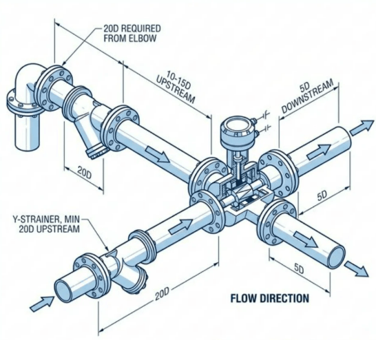
Turbine meters are sensitive to disturbed velocity profiles. The standard requirement is:
- Upstream: 10–15 pipe diameters of unobstructed straight run
- Downstream: 5 pipe diameters of straight run
With upstream obstructions, increase straight run:
| Upstream Obstruction Type | Required Upstream Straight Run |
|---|---|
| Single 90° elbow, tee, strainer, thermowell | 20× pipe diameter |
| Partially open valve | 25× pipe diameter |
| Two elbows in different planes / spiral flow | 50× pipe diameter (or add flow straighteners) |
👉 Detailed straight run rules: Turbine Flow Meter Straight Run Requirement: What’s the Standard?
Upstream Y-Strainer (Mandatory for Particle Protection)
If the liquid contains suspended solids or particle sizes above 75 μm, a flushing Y-strainer or motorized cartridge filter must be installed at least 20 pipe diameters upstream. Failing to install a strainer is the single most common cause of rotor bearing damage in turbine meters.
Lessons from the Field: A Chemical Batching Line Case
Application: IPA (isopropyl alcohol) batching in a pharmaceutical intermediate plant.
Problem: A DN25 turbine meter showed erratic readings within 6 weeks of installation. The K-factor had drifted by over 2%, well outside the ±0.5%R spec.
Root cause: The upstream Y-strainer was installed immediately adjacent to a 90° elbow, and the strainer mesh had not been cleaned in 4 weeks. The combined effect of strainer pressure drop and disturbed flow profile degraded accuracy.
Solution: Relocated the strainer 20 diameters upstream of the elbow (not immediately downstream of it), added a scheduled 2-week cleaning interval logged in the plant CMMS. Accuracy immediately recovered to ±0.4%R.
Lesson: Strainer location affects upstream flow profile just as much as elbows do. Count straight pipe from the strainer, not from the nearest elbow.
Selection Decision Matrix: Which Configuration Is Right for You?
Use this matrix to arrive at a configuration after you’ve verified fluid compatibility and flow range. This table is the information gain element absent in competitor articles — no top-10 ranking page provides a scenario-based decision matrix like this.
| Application Type | Accuracy Priority | Recommended Accuracy Class | Recommended Connection | Recommended Output | Special Requirement |
|---|---|---|---|---|---|
| Water utility billing | High | ±0.5%R | Flange | Pulse + 4–20 mA | Install upstream of any pump |
| Fuel custody transfer | Very high | ±0.2%R (custom) | Flange | Pulse (high-res) | Temperature compensation recommended |
| Chemical process dosing | Moderate | ±1%R | Thread or Wafer | Pulse or 4–20 mA | Verify 304/316 SS compatibility |
| Food & beverage (hygienic) | Moderate–High | ±0.5%R | Tri-clamp | 4–20 mA | 316L SS + electropolish; CIP-compatible |
| Batch production control | High | ±0.5%R | Thread or Flange | Pulse → batch controller | Flow computer with dribble-flow cutoff |
| Hydraulic oil circuit | Moderate | ±1%R (after calibration) | Thread | Pulse | Real-fluid calibration; monitor temperature |
| Remote/off-grid monitoring | Moderate | ±1%R | Thread or Flange | Battery-powered pulse | 3.6 V lithium internal battery |
| Explosion-hazard zone | Moderate–High | ±0.5%R | Flange | 4–20 mA (HART) | Exd II CT6 Gb rated; M20×1.5 conduit entry |
Common Issues & Troubleshooting Guide
👉 Comprehensive troubleshooting: Turbine Flow Meter Troubleshooting: How to Fix Common Issues?
| Symptom | Most Likely Cause | Recommended Action |
|---|---|---|
| Reading too high | Air entrainment in liquid; flashing upstream of meter | Check upstream pressure; add backpressure valve downstream; purge air |
| Reading too low / K-factor drift | Bearing wear (over-ranging); strainer clogged | Check/clean strainer; verify flow velocity ≤10 m/s continuous; recalibrate |
| Erratic or noisy pulse signal | Magnetic particle contamination; vibration; EMI interference | Install strainer; check grounding; reroute signal cable away from power cables |
| No signal / rotor doesn’t spin | Foreign object jamming rotor; fluid not flowing; pickup coil failure | Inspect and clean rotor; verify flow exists; check pickup coil resistance (typically 500–3000 Ω) |
| Zero drift at no-flow condition | Pickup coil magnetic drag; vibration from nearby equipment | Configure low-flow cutoff (small signal cutoff) in converter; isolate vibration source |
| Cavitation damage on rotor blades | Downstream pressure too low; pressure drop across meter > vapor pressure margin | Ensure downstream pressure ≥ 1.25× vapor pressure + 2× pressure drop across meter |
Industrial Applications
Liquid turbine flow meters are widely used across industries where clean, low-viscosity liquid flow measurement requires high accuracy with pulse output compatibility:
- Oil & Gas: Refined product pipelines, marketing terminal custody transfer, tank farm metering, mobile fuel dispensing
- Chemical Processing: Solvent consumption monitoring, chemical dosing accuracy verification, process batch control
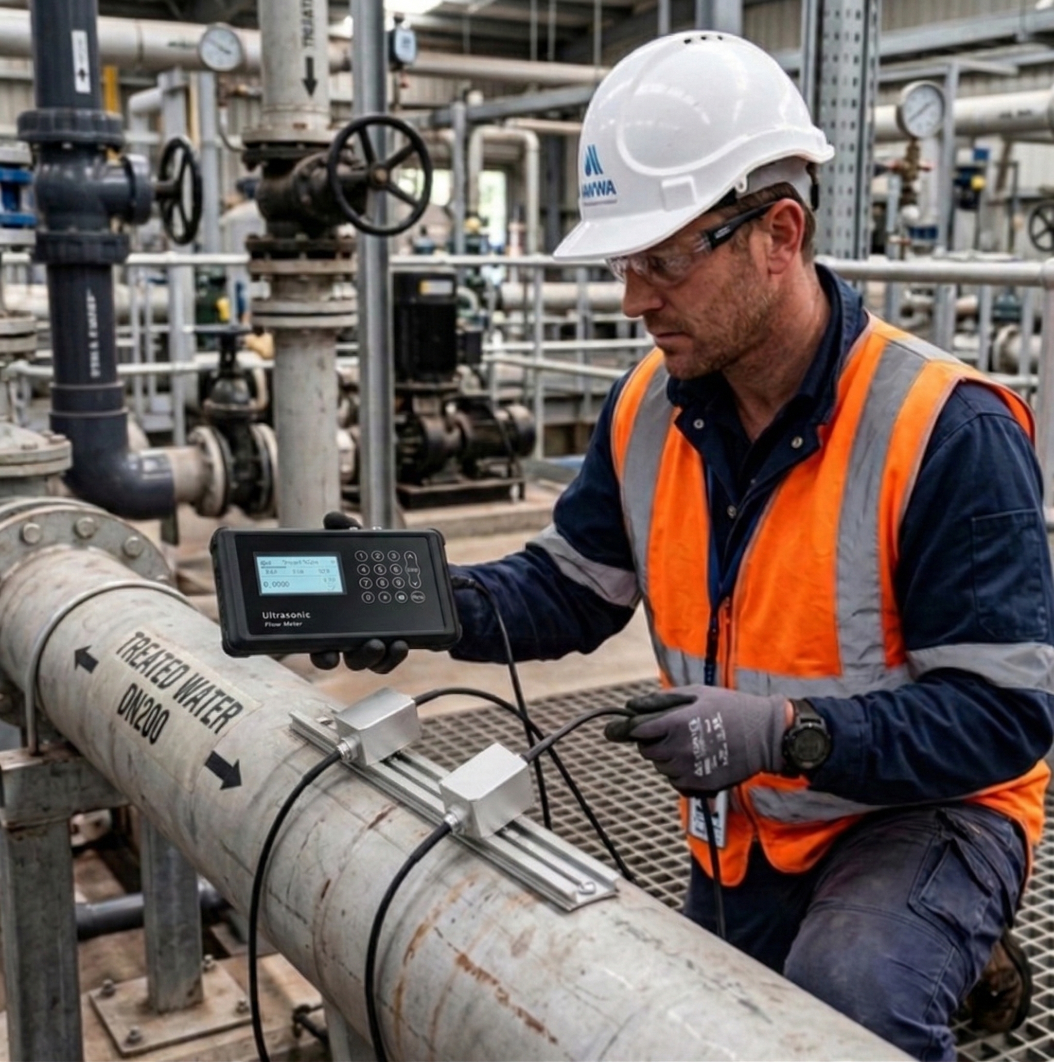
- Water Treatment: Treated water distribution billing, reverse osmosis permeate measurement, dosing chemical injection rate
- Food & Beverage: Sanitary tri-clamp configurations for beverages, edible oils, syrups, and process water (CIP-compatible)
- Pharmaceutical: Purified water (PW) consumption monitoring, WFI distribution metering (316L + electropolished)
- Power Generation: Cooling water makeup, demineralized water measurement, fuel oil consumption tracking
👉 See also: Why Choose Turbine Flow Meters for Industrial Applications?
👉 And: Turbine Flow Meter for Water: Is It the Right Choice?
Frequently Asked Questions
Q1: What liquids can a liquid turbine flow meter measure?
Liquid turbine flow meters are designed for clean, low-viscosity liquids with kinematic viscosity ≤5×10⁻⁶ m²/s at working temperature—such as water, light oils, alcohols, fuels, and chemical solvents. Liquids with higher viscosity can still be used after real-liquid calibration at actual operating conditions. The liquid must be free of fibers, large particles (>75 μm), and ferromagnetic impurities.
Q2: What is the accuracy of a liquid turbine flow meter?
Soaring Instrument liquid turbine flow meters achieve ±1%R or ±0.5%R standard accuracy. High-precision models reach ±0.2%R (custom order). Short-term repeatability: 0.05%–0.2%. The "%R" designation means error is relative to actual reading—not full scale—giving better real-world performance at partial loads compared to FS-rated meters.
Q3: How many diameters of straight pipe do they require?
Standard: 10–15 pipe diameters upstream, 5 downstream. Increase to 20–25 diameters if elbows, tees, or valves exist upstream. Install a Y-strainer at least 20 pipe diameters upstream of the meter to protect the rotor from particles.
Q4: Turbine vs. electromagnetic flow meter for clean liquids — which to choose?
Choose turbine when: fluid may be non-conductive (oils, solvents), you need high-accuracy pulse output for trade settlement, or cost is a constraint.
Choose electromagnetic when: fluid is conductive and may contain trace solids or slurries, or you need zero pressure loss and no moving parts for long maintenance intervals.
Q5: Can turbine flow meters measure reverse flow?
Standard liquid turbine flow meters measure unidirectional flow only. For bidirectional measurement applications, specify a dual-channel converter at time of order. Always confirm flow direction before installation.
Q6: What connection types are available?
Thread, Flange, Tri-clamp (Sanitary/Clamp), and Wafer. Thread and tri-clamp are common for small diameters and sanitary applications; flanged connections suit industrial pipelines with higher pressure ratings.
Q7: How do I size a liquid turbine flow meter correctly?
Size the meter so your average expected flow is 60%–75% of the meter’s maximum rated flow. Avoid continuous operation above 90% of maximum flow (accelerated bearing wear) or below 30% of maximum flow (reduced linearity). If pipe velocity is naturally below 0.3 m/s, select a meter one size smaller than the pipe diameter.
Conclusion: 5 Keys to Correct Liquid Turbine Flow Meter Selection
- Verify fluid compatibility first — clean, particle-free, low-viscosity (≤5×10⁻⁶ m²/s). If uncertain, request real-liquid calibration.
- Size for 60%–75% of rated flow at average conditions — avoid the low-flow nonlinear zone and high-flow bearing wear zone.
- Match accuracy class to your commercial or process need — ±0.5%R for trade settlement, ±0.2%R for custody transfer, ±1%R for general monitoring.
- Select connection type based on pipe size and hygiene requirements — tri-clamp for sanitary, flanged for industrial, threaded for compact installations.
- Plan installation carefully — install a Y-strainer 20D upstream and provide adequate straight-run pipe. Most field accuracy problems trace back to installation, not the meter itself.
Ready to Select Your Liquid Turbine Flow Meter?
Shanghai Soaring Instrument Technology Co., Ltd. manufactures liquid turbine flow meters compliant with JB/T 9246-1999, available in accuracy classes ±1%R, ±0.5%R, and ±0.2%R (custom), with connection types Thread, Flange, Tri-clamp, and Wafer.
Tell us your application parameters and we’ll recommend the right configuration:
- 📧 [email protected]
- 📞 +86-13585991410
- 🌐 Contact Us
Related Articles
- Turbine Flow Meter Working Principle: How Does It Operate?
- Turbine Flow Meter K-Factor Calculation: Know the Numbers for Precision
- Turbine Flow Meter Straight Run Requirement: What’s the Standard?
- Turbine Flow Meter Troubleshooting: How to Fix Common Issues?
- Turbine Flow Meter for Water: Is It the Right Choice?
- How Do Turbine and Electromagnetic Flow Meters Compare?
- Why Choose Turbine Flow Meters for Industrial Applications?
- Understanding Turbine Flow Meter Turndown Ratio: Why Is It Critical?