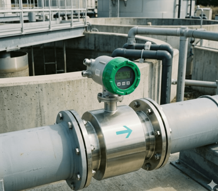
Electromagnetic flow meters (EMFs) are the backbone of fluid measurement in industries like water treatment, chemical processing, and food production. However, 75% of measurement errors originate from incorrect configuration, according to a 2023 report by ABB. In this guide, we’ll walk through the critical steps to configure your electromagnetic flow meter effectively—and avoid costly mistakes.
Step 1: Pre-Configuration Checklist
Before powering up your EMF, verify these essentials:
✔️ Hardware Requirements
| Component | Specification |
|---|---|
| Pipe Condition | Full pipe (no gas bubbles) |
| Grounding | Dedicated earth rod (<4Ω resistance) |
| Electrodes | Clean, free from coating/corrosion |
✔️ Fluid Properties
- Minimum Conductivity: ≥5 μS/cm (e.g., tap water=50-800 μS/cm; ultrapure water=0.055 μS/cm cannot be measured)
- Flow Profile: Turbulent flow (Re > 4,000) preferred
Step 2: Key Parameter Settings
Access your EMF’s interface (local display or HART/Modbus connection) and configure:
a) Flow Unit & Range
- Set
Unitto match process requirements (e.g., m³/h, GPM). - Enter
Upper Range Value (URV)= Max expected flow (avoid oversizing by >20%).
Example: - Pipe ID: 100mm → Max flow 150 m³/h → Set URV=180 m³/h
b) Fluid Type Profiles
Pre-load conductivity/temperature compensation curves for:
- Water: Standard linear scaling
- Slurries: Enable slurry mode (adjusts noise filtering)
- Corrosive liquids: Activate electrode polarity reversal to reduce coating buildup
c) Output Signals
| Signal Type | Typical Settings |
|---|---|
| 4-20mA Analog | 4mA=0 flow; 20mA=URV |
| Pulse Output | 1 pulse = 1L (calibrate with K-factor) |
| Digital (Modbus) | Set device address & baud rate |
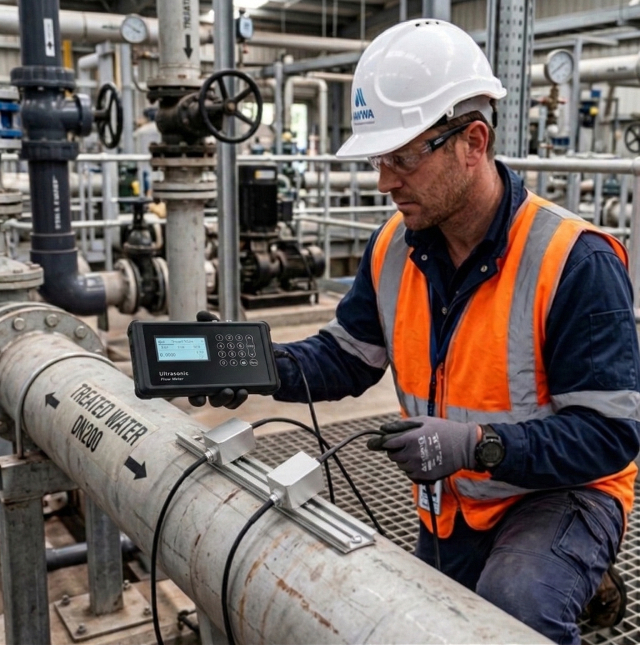
Step 3: Field Calibration Techniques
Zero-Point Calibration
- Ensure pipes are completely filled with stationary fluid.
- Navigate to:
Menu → Calibration → Zero Adjust. - Confirm stability (±0.1% of span for 30 seconds).
⚠️ Critical: Perform after mechanical installation and power cycling.
Step 4: Avoid These 3 Costly Configuration Errors
Mistake 1: Incorrect Electrode Axis Alignment
- ✅ Fix: Align electrodes perpendicular to piping supports to minimize vibration errors.
Mistake 2: Ignoring Cable Specifications
- ❌ Cat6 UTP cables → EMI interference
- ✅ Use shielded twisted-pair (STP) cables with grounded drain wires.
Mistake 3: Skipping Empty Pipe Detection (EPD)
- Configure EPD thresholds based on dielectric constant:
- Water: ε=80 → Set cutoff at ε=10
- Oil: ε=2-5 → Set cutoff at ε=1.5
Advanced Configuration Tips
For Slurry Applications
- Enable frequency shift mode (Fuji Electric patent) to suppress solids-induced noise.
- Set excitation frequency to 6.25Hz (default 3.125Hz) for faster bubble rejection.
For Battery-Powered Units
- Reduce update interval to 5s (from 1s) → Extends battery life by 400%
Troubleshooting Configuration Issues
| Symptom | Likely Cause | Diagnostic Tool |
|---|---|---|
| Unstable readings | Air bubbles/partial pipe | Strouhal number analysis |
| Zero drift | Ground loop interference | Oscilloscope (look for 50/60Hz noise) |
| No pulse output | Incorrect K-factor | Calibrate with master meter |
Need Professional Support?
At Soaring Instrument, our team has configured over 2,500 electromagnetic flow meters across 18 industries. Explore our:
- Pre-Configuration Checklist (Free Download)
- Industry-Specific Configuration Guides
Still have questions? Book a live demo with our engineers → Contact Us