Installing the wrong flow measurement system can lead to costly miscalculations. Understanding Faraday’s Law helps select the perfect magmeter for conductive fluid applications.
Electromagnetic flowmeters operate using Faraday’s Law of Induction – when conductive fluid flows through a magnetic field, it generates a voltage perpendicular to both flow and field directions. This induced EMF (electromotive force) is directly proportional to flow velocity, allowing precise measurement without moving parts or flow obstruction.
Faraday’s Law in Flow Measurement
This 19th century physics principle powers modern industrial flow measurement. Let’s examine how it translates into reliable pipeline instrumentation.
What is Faraday’s Law of Electromagnetic Flow Meter?
The foundational physics behind all magmeter operations.
Faraday’s Law states that a voltage is induced when a conductor moves through a magnetic field. In flowmeters, the conductive fluid acts as the moving conductor, with electrodes detecting millivolt signals proportional to average flow velocity (V = B×L×v where B=magnetic flux density, L=electrode spacing, v=fluid velocity).
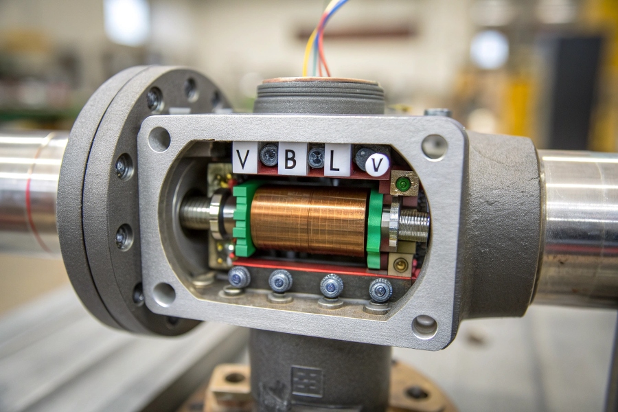
Magmeter Cross-Section
The practical implementation involves careful engineering:
Key Design Components
Magnetic Coils
- Generate controlled DC or AC magnetic field (typically 0.01-0.1 Tesla)
- Modern pulsed DC systems reduce power consumption
Measurement Electrodes
- Stainless steel or specialized alloys (Hastelloy for corrosive fluids)
- Precisely spaced to establish known ‘L’ dimension
Liner Material
- PTFE, ceramic, or rubber isolates electrodes from pipe
- Must withstand fluid chemistry and temperature
Signal Converter
- Amplifies microvolt signals (0.5-5mV typical)
- Filters out electrical noise (60/50Hz interference)
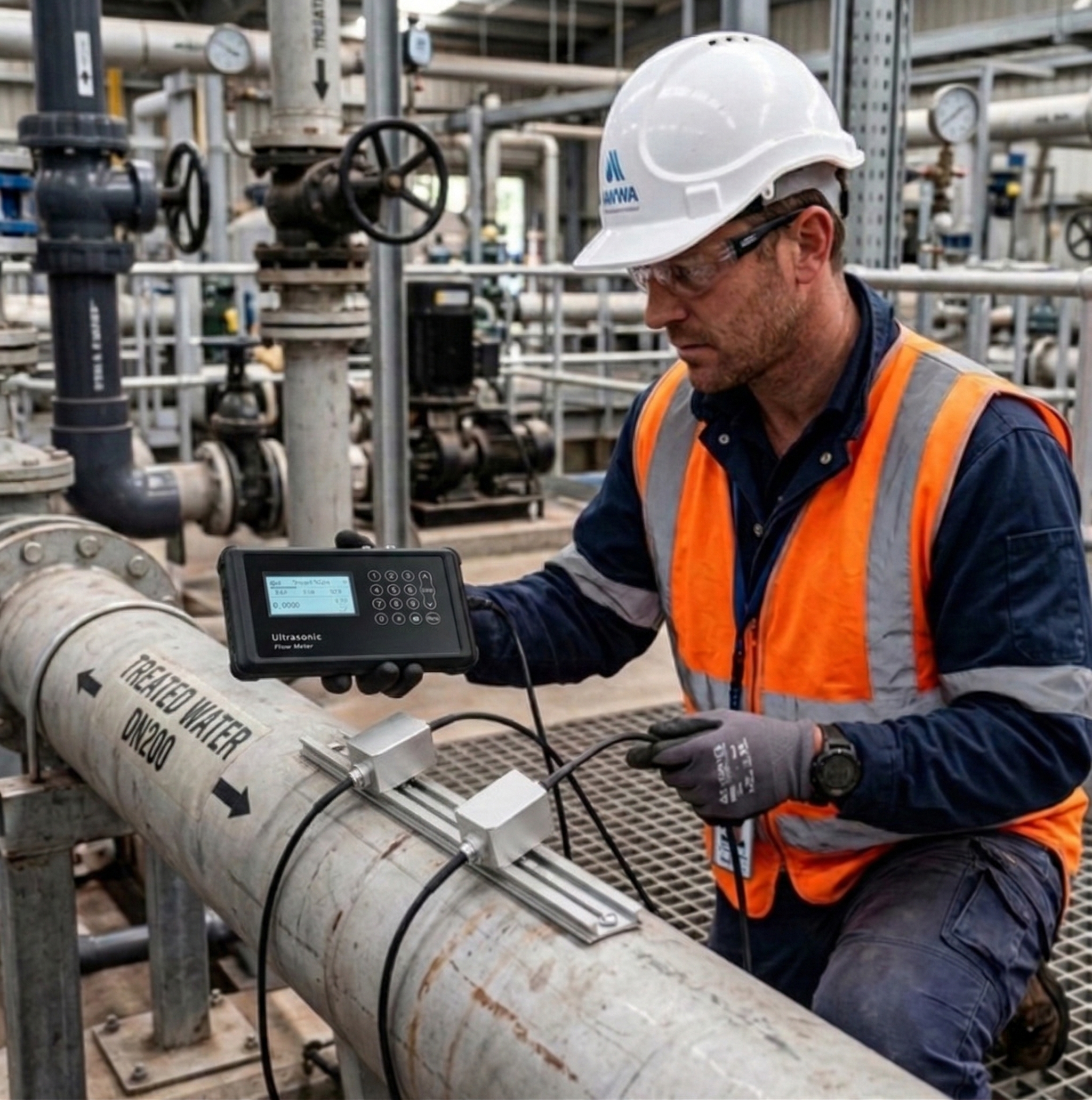
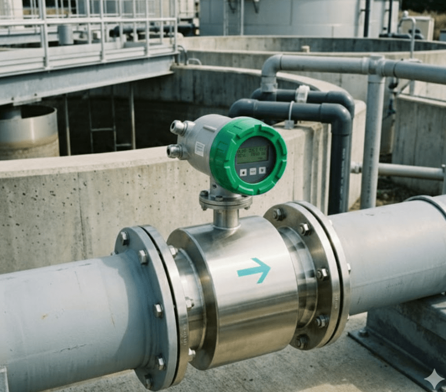
How Does an Electromagnetic Flowmeter Work?
From physics principle to industrial measurement.
The meter’s coils create a transverse magnetic field across the pipe. Flowing conductive fluid generates a voltage detected by opposing electrodes. The transmitter processes this signal using Faraday’s equation (Q = V×A where Q=flow rate, V=velocity, A=pipe area) to calculate volumetric flow independent of density, pressure, or viscosity.
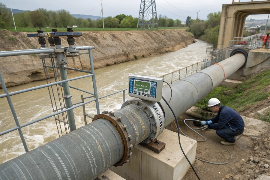
Measurement Process Breakdown
Real-world operation requires addressing several technical challenges:
Practical Measurement Considerations
| Parameter | Impact | Solution |
|---|---|---|
| Fluid Conductivity | Below 5 μS/cm gives weak signal | Add electrolytes or choose different technology |
| Flow Profile | Non-symmetric flow creates error | Install with 5D upstream straight pipe |
| Electrode Fouling | Coating insulates electrodes | Increase velocity (>1 m/s) or use cleaning systems |
| Electrical Noise | Stray voltages distort signal | Proper grounding and shielded cables |
| Bubble Content | Gas voids disrupt conductivity | Mount vertically (upward flow) |
What is Faraday’s Law Based on Its Importance in Electromagnetism?
Why this 1831 discovery remains vital today.
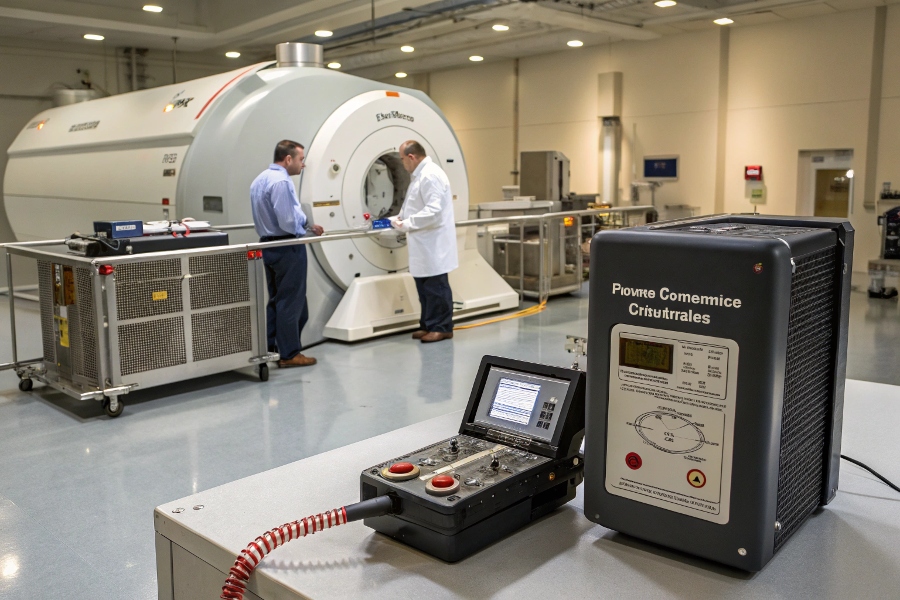
Faraday’s Law forms the basis for all electromagnetic induction devices – from power generators to MRI machines. For flow measurement, it provides contactless, obstruction-free operation with linear response ideal for custody transfer (0.2-0.5% accuracy) and no pressure drop – impossible with mechanical meters.
Faraday’s Law Applications
The law’s universality enables diverse implementations:
Industrial Measurement Variations
Wetted Electrode Designs
- Traditional contact method
- Suitable for clean conductive fluids
- Example: Drinking water distribution
Capacitive Electrode Designs
- Non-contact measurement
- Handles coatings/deposits
- Example: Wastewater sludge lines
Insertion Magmeters
- For large pipes (>300mm)
- Reduced installation cost
- Example: Cooling water intakes
Battery-Powered Magmeters
- No external power needed
- 10+ year battery life
- Example: Agricultural irrigation
What is the Basic Principle of a Flow Meter?
How magmeters compare to other technologies.
All flow meters measure by either: 1) Tracking fluid displacement (positive displacement), 2) Sensing flow velocity (mag, ultrasonic, vortex), or 3) Measuring mass directly (Coriolis). Magmeters uniquely require no moving parts while measuring conductive liquids with high accuracy and minimal maintenance – making them ideal for corrosive/abrasive flows where other meters fail.
![]()
Technology Tradeoffs
Understanding measurement alternatives helps proper selection:
Measurement Technology Matrix
| Principle | Example | Best For | Limitation |
|---|---|---|---|
| Electromagnetic | Magmeter | Conductive liquids (>5 μS/cm) | Doesn’t work with hydrocarbons |
| Vortex | Vortex meter | Steam/gas measurement | Pressure drop from bluff body |
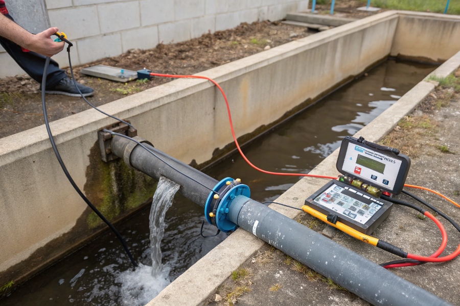
| Ultrasonic | Clamp-on meter | Large pipe retrofits | Needs acoustic reflectors |
| Coriolis | Mass flow meter | Custody transfer liquids | High cost for large lines |
| Positive Displacement | Gear meter | High viscosity oils | Moving parts wear out |
Installation Best Practices
Proper setup ensures specified accuracy.
Orientation Rules
- Avoid top-of-pipe mounting (air bubble risk)
- Preferred: Horizontal with electrodes at 3/9 o’clock
Grounding Requirements
- Dedicated ground ring for plastic pipes
- Ground electrode for conductive pipes
Flow Conditioning
- 5D upstream straight run minimum
- Flow straighteners for disturbed profiles
Electrical Isolation
- Insulating gaskets at flanges
- Lightning protection for outdoor units
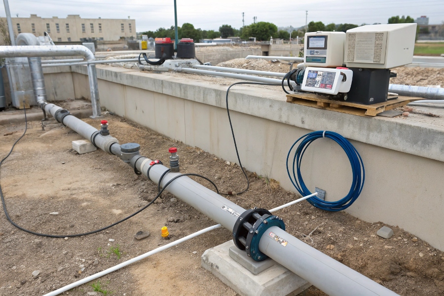
Proper Installation Methods
Signal Processing Innovations
Modern electronics overcome traditional limitations.
Digital signal processing now enables: auto-zero correction for electrode drift, frequency analysis to identify bubbles/solids, and smart diagnostics predicting maintenance needs. Some models integrate conductivity measurement to verify proper operating conditions.
Advanced Feature Comparison
| Feature | Traditional | Smart Magmeter |
|---|---|---|
| Electrode Check | Manual inspection | Continuous impedance monitoring |
| Empty Pipe Detection | Separate sensor | Capacitance-based automatic |
| Noise Filtering | Fixed frequency | Adaptive digital filtering |
| Diagnostics | None | Coil health, liner wear alerts |
| Communication | 4-20mA only | HART, Modbus, PROFIBUS |
Future Developments
Where magmeter technology is heading.
Wireless Power Transfer
- Eliminate cables in hazardous areas
- Energy harvesting from flow vibration
Graphene Electrodes
- Ultra-thin corrosion-resistant layers
- Improved signal-to-noise ratio
AI Predictive Maintenance
- Pattern recognition for coating buildup
- Optimal cleaning cycle calculation
IoT Integration
- Cloud-based flow monitoring
- Automated calibration tracking
Conclusion
Electromagnetic flowmeters transform Faraday’s 1831 discovery into precise industrial measurement. By inducing voltage in moving conductive fluids, they provide maintenance-free, obstructionless flow data critical for water, chemicals, and slurries. Proper installation respecting conductivity requirements and flow profiles ensures these meters deliver their full 0.5% accuracy potential across decades of service. While limited to conductive media, their reliability makes magmeters the first choice wherever fluid conductivity