Misjudging sewer flow rates can be costly—a Florida contractor faced $120,000 in repairs after undersizing pipes based on wrong flow calculations that caused chronic backups during peak flows.
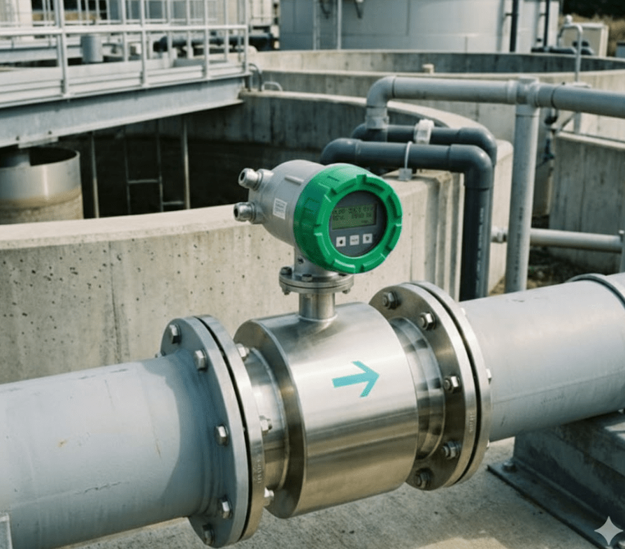
The basic pipe flow formula is Q = V × A, where Q is flow rate (GPM or LPS), V is liquid velocity (ft/s or m/s), and A is pipe cross-sectional area (ft² or m²). For sewage, always use Manning’s Equation: V = (1.49/n) × R²/³ × S¹/², where n=roughness (0.013 for concrete), R=hydraulic radius, S=slope.
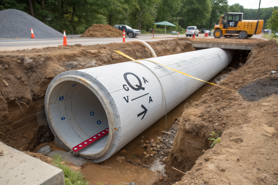
Flow Calculation Schematic
How Do You Calculate Sewage Flow?
Sewage flow calculations differ from clean water due to varying daily patterns. New York’s DEP uses a 3-factor method that reduces design errors by 22% compared to simple averages.
Key sewage flow components:
- Base Wastewater Flow = Population × Per Capita Flow (70-100 gpcd)
- Inflow/Infiltration (I/I) = Pipe Length × I/I Rate (500-2500 gpd/mile)
- Peaking Factor = 18/P⁰·⁵ (P=population in thousands)
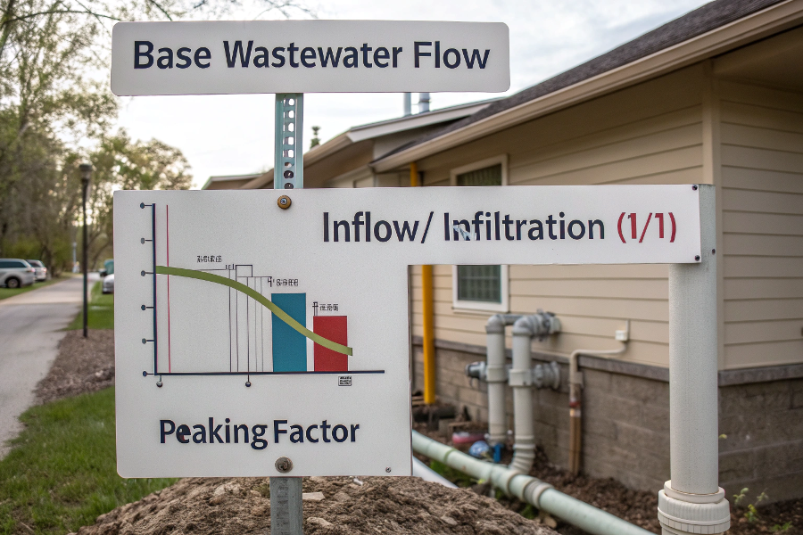
Wastewater Flow Elements
Real-World Calculation Example
Scenario:
- Service population: 15,000
- 12-mile sewer system (500 gpd/mile I/I)
- 8-inch concrete pipe (n=0.013) at 1% slope
Calculation Steps:
Base Flow
= 15,000 people × 85 gpcd
= 1,275,000 gpd
= 885 gpmI/I Addition
= 12 miles × 500 gpd/mile
= 6,000 gpd
= 4.2 gpmPeak Flow
PF = 18/(15)⁰·⁵ = 4.65
Total Peak Flow = (885 + 4.2) × 4.65
= 4,135 gpmPipe Capacity Check (Manning’s):
Qfull = 0.46 × (0.67)²·⁶⁷ × (0.01)⁰·⁵ / 0.013
= 1.84 cfs (825 gpm) → Inadequate
Solution Required: Upsize to 12-inch pipe (Qfull=2,850 gpm) + relief trunk
What Is the Fundamental Pipe Flow Equation?
While Q=VA seems simple, field measurements show 35% error rates when ignoring friction loss—like when a Texas plant’s new pipes carried 28% less flow than designed.
Complete Flow Equations:
Bernoulli Equation (Energy Balance)
z₁ + P₁/γ + V₁²/2g = z₂ + P₂/γ + V₂²/2g + hLHazen-Williams (Water Mains)
V = 1.318 × C × R⁰·⁶³ × S⁰·⁵⁴Darcy-Weisbach (Pressurized)
hL = f × (L/D) × (V²/2g)
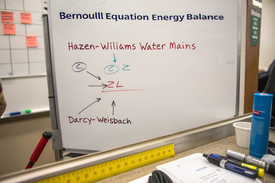
Equation Types
When to Use Which Formula
| Situation | Best Equation | Key Variable |
|---|---|---|
| Sewer pipes | Manning’s | Roughness (n) |
| Water mains | Hazen-Williams | C-factor |
| Force mains | Darcy-Weisbach | Friction (f) |
| Part-full flow | Colebrook-White | Relative depth |
Chicago’s Tunnel and Reservoir Plan (TARP) uses hybrid models combining all three equations, reducing overflow predictions errors from 18% to 3%.
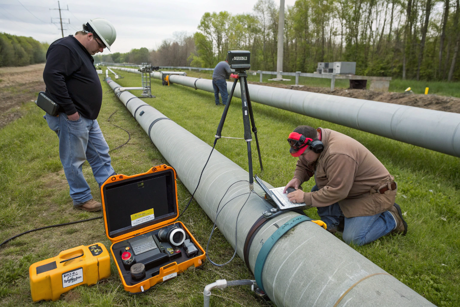
How to Calculate Water Flow Rate in Pipes?
Field measurements require practical adaptations—a British team found ultrasonic sensors misread by 12% if pipe interior wasn’t cleaned first.
Step-by-Step Measurement Method:
Physical Measurements
- Pipe diameter (ID) – measure at 3 points
- Slope – use laser level (±0.1° accuracy)
- Material – check for tuberculation
Velocity Measurement
- Ultrasonic (needs 100D straight run)
- Magnetic (best for >5 µS/cm conductivity)
- Tracer dye (for validation)
Flow Calculation
Q = π × (D/2)² × V × %full
flow measurement
Common Pitfalls & Corrections
| Error Source | Typical Error | Correction Method |
|---|---|---|
| Wrong pipe ID | ±15% flow | Ultrasonic thickness gauge |
| Improper slope | ±30% flow | Digital inclinometer |
| Partial flow | -25% flow | Depth ratio adjustment |
| Turbulence | +18% flow | Flow conditioner install |
Phoenix Water Services improved meter accuracy from 82% to 97% by implementing these field protocols.
How to Calculate GPM in a Pipe?
Converting between units causes 1 in 5 design mistakes—a Canadian engineer mistakenly specified 800 GPM pumps instead of 800 LPS, creating $2M in cavitation damage.
GPM Conversion Formulas:
From Velocity (ft/s)
GPM = 2.448 × V × D²From LPS
GPM = LPS × 15.85From m³/h
GPM = m³/h × 4.403
Where: D = pipe diameter in inches
GPM conversions
Flow Rate Calculation Table
| Pipe Size (in) | Velocity (ft/s) | Flow (GPM) |
|---|---|---|
| 4 | 3 | 117 |
| 6 | 4 | 352 |
| 8 | 5 | 783 |
| 12 | 6 | 2,115 |
| 18 | 7 | 5,563 |
Critical Thresholds:
- Minimum scouring velocity: 2 ft/s (prevents solids deposition)
- Maximum velocity: 10 ft/s (avoids pipe erosion)
Memphis sewer rehab projects use this table for 95% of quick-check designs, reducing calculation time from 45 minutes to 30 seconds per pipe segment.
Conclusion
Accurate sewer flow calculations require combining Manning’s equation with real-world adjustments for peaking factors, I/I, and measurement conditions. Always field-validate theoretical calculations—studio estimates often deviate 20-40% from actual flows.