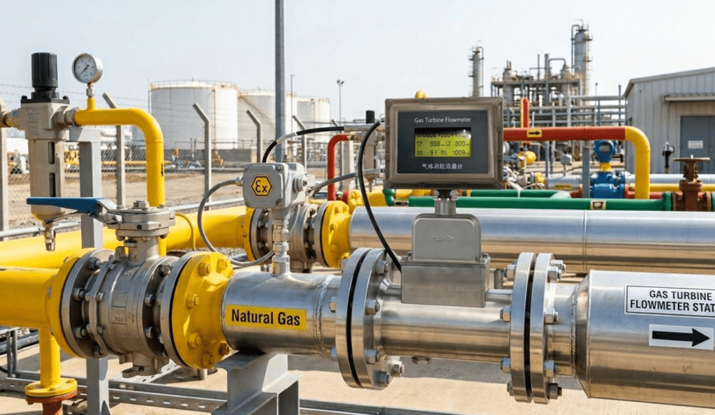
Gas turbine flow meter in service on a natural gas distribution pipeline — flanged installation with integrated LCD display showing real-time flow data.
Every month, our application engineering team receives the same question from gas plant operators: "We need a natural gas flow meter for custody transfer — what’s the most reliable option at our flow range?"
The answer, in most cases, is a gas turbine flow meter.
Over years of supplying flow instrumentation to oil and gas facilities, industrial plants, and distribution networks, we’ve learned that gas turbine meters succeed when they’re correctly selected, properly installed, and methodically maintained — and fail when any of those three elements are overlooked.
This guide consolidates everything we know about deploying gas turbine flow meters in natural gas measurement applications: the physics behind them, how to size them correctly, installation requirements, common failure modes, and the best practices that make the difference between ±1% accuracy and costly measurement errors.
Quick Answer: A gas turbine flow meter measures volumetric flow rate by counting rotor revolutions generated by the gas stream. For natural gas applications, it delivers accuracy of ±1.0% to ±1.5%, a wide flow range with turndown ratios up to 20:1, and a reliable pulse output signal suitable for SCADA integration. It is one of the preferred meters for custody transfer and trade billing across a wide variety of gas industry applications — from city gate stations to industrial burner control.
For background on how turbine meters compare with other technologies, see our guide: How Do Different Flow Meter Technologies Compare in Performance and Application?
What Is a Gas Turbine Flow Meter?
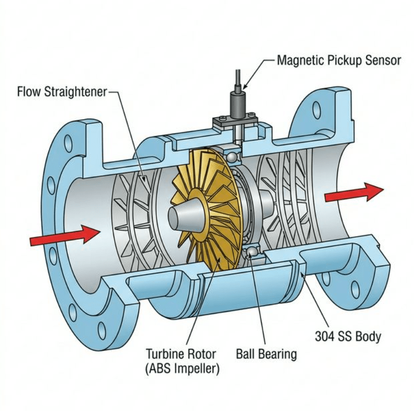
Cutaway diagram of a gas turbine flow meter: gas flow (→) passes over the multi-bladed rotor, spinning it at a speed proportional to velocity. The magnetic pickup sensor converts blade passages into a pulse output signal.
A gas turbine flow meter is a velocity-based measurement device. Inside the meter body — typically machined from 304 or 316 stainless steel — sits a multi-bladed rotor suspended between upstream and downstream flow straighteners. As gas passes through, it spins the rotor at a speed directly proportional to the average gas velocity.
A non-contact magnetic or RF pickup detects each blade passing, generating a pulse. The output signal frequency (Hz) converts directly to volumetric flow rate. Cumulative pulse count gives totalised volume.
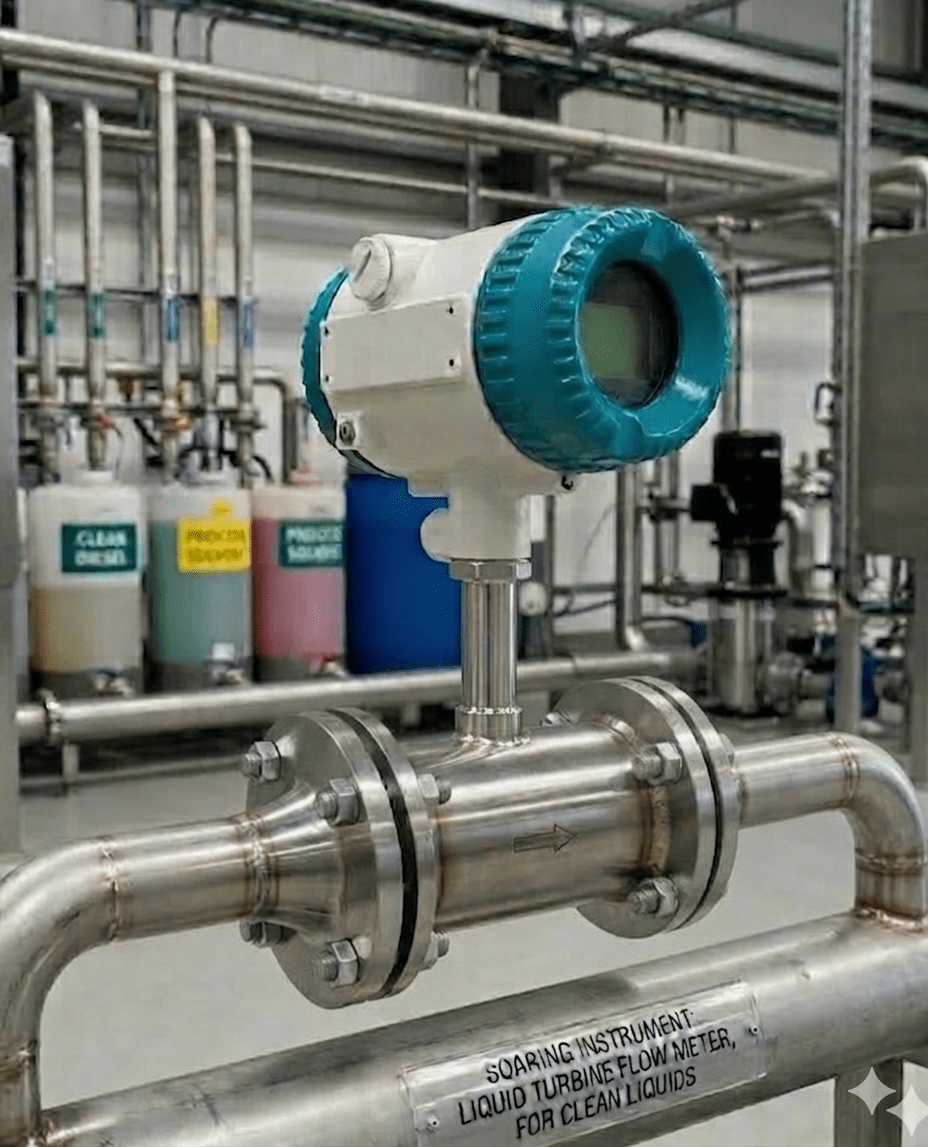
Gas Turbine vs. Liquid Turbine Flow Meters
Many engineers assume the two are interchangeable. They are not.
| Feature | Gas Turbine Flow Meter | Liquid Turbine Flow Meter |
|---|---|---|
| Rotor Design | Lightweight, low-inertia blades (anti-corrosion ABS or aluminum alloy) | Denser stainless steel blades |
| Bearing Spec | Ball bearings, rated for low-lubricity gas | Ball or sleeve bearings, lubricated by liquid |
| Velocity Range | Lower velocity threshold optimized for gas (contact factory for sizing) | Optimized for liquid velocity profiles |
| Body Material | 304 SS body / cast aluminum; ABS or aluminum alloy impeller | 304 or 316 SS throughout |
| K-Factor Stability | Requires volume correction (T, P, Z) for standard volume output | Stable across low-viscosity liquids |
| Application | Natural gas, air, nitrogen, industrial gases | Clean liquids with kinematic viscosity ≤5×10⁻⁶ m²/s |
The core distinction: because gas is compressible, a gas turbine flowmeter measures volume at working conditions. To obtain standard volume (Nm³/h or SCFH) for billing and custody transfer, you must apply temperature and pressure compensation — either via an integrated flow computer or an external volume corrector.
Understanding K-Factor in Gas Turbine Meters
The K-factor (meter factor) is the number of output pulses per unit volume — for example, 120 pulses per cubic meter. Every gas turbine meter is factory-calibrated to establish its K-factor across the operating flow range. This K-factor is stable over a wide variety of operating conditions, which is what makes turbine meters suitable for trade billing without frequent recalibration.
However, K-factor can drift if the rotor sustains physical damage from entrained particles, or if bearing wear increases friction. This is why upstream filtration and periodic calibration verification are essential best practices — K-factor drift of as little as 0.3% represents significant financial exposure in high-volume custody transfer applications.
For a comprehensive comparison of turbine meter technologies, see our article: How Do Turbine and Electromagnetic Flow Meters Compare?
Why Gas Turbine Flow Meters Are Preferred for Natural Gas
The natural gas flow meter landscape is crowded — vortex meters, ultrasonic meters, Coriolis, differential pressure orifice plates. So why do gas operators consistently return to turbine meters?
Based on our project experience, five reasons dominate:
1. Wide Flow Range at High Accuracy
Gas turbine flow meters deliver high accuracy (±1.0%R for larger diameters, ±1.5%R for smaller) across a wide flow range. Our DN100 model covers a turndown ratio of 1:20, meaning it measures accurately from 40 m³/h to 800 m³/h on a single meter body. This is critical in gas networks where demand fluctuates dramatically between peak and off-peak hours.
2. Direct Volume Pulse Output
The frequency output signal integrates cleanly with RTUs, SCADA systems, and gas volume correctors. No analog-to-digital conversion artifacts. Each pulse represents a fixed volume (the K-factor), making totalisation inherently accurate.
3. Low Pressure Loss
Pressure drop through a gas turbine meter at normal operating conditions is typically 0.1 to 2.5 kPa — far lower than orifice plates at comparable accuracy. For gas pipeline operators, this translates directly to compression cost savings.
4. Proven in Custody Transfer
Gas turbine meters have a decades-long track record in custody transfer and trade billing. International standards including ISO 9951 (Measurement of gas flow in closed conduits — turbine meters) govern their performance requirements. The American Gas Association’s AGA Report No. 7 provides additional guidance specifically for turbine meters in natural gas transmission and distribution. Regulators and utilities worldwide accept them as primary meters.
5. Compact and Field-Serviceable
Our gas turbine units (DN25 to DN250) are compact enough for skid-mounted measurement installations. The cartridge-style internal assembly allows field inspection and rotor replacement without removing the meter body from the pipeline — a significant advantage in continuous-operation gas plants.
Relevant Reading: Why Choose Turbine Flow Meters for Industrial Applications?
Gas Turbine Flow Meter Technical Specifications
All parameters verified against Soaring Instrument product catalog. Do not specify meters based on generic data sheets.
| Parameter | Specification |
|---|---|
| Available Diameters | DN25, DN40, DN50, DN80, DN100, DN150, DN200, DN250 |
| Accuracy Class | ±1.5%R (standard) / ±1.0%R (calibrated) |
| Repeatability | 0.05%–0.2% (enables high accuracy after calibration; preferred for trade settlement) |
| Turndown Ratio | 1:10 / 1:20 / 1:30 (contact factory for diameter-specific mapping) |
| Medium Temperature | -10°C to +100°C |
| Ambient Temperature | -10°C to +100°C |
| Atmospheric Pressure Operating Range | 86–106 kPa |
| Relative Humidity | 5%–90% |
| Pressure Loss | 0.1–2.5 kPa at working conditions |
| Body Material | 304 stainless steel / cast aluminum |
| Impeller Material | Anti-corrosion ABS or high-quality aluminum alloy |
| Output Signal | Three-wire pulse (frequency output) / 4–20 mA / RS-485 (Modbus) / IC card |
| Power Supply | Built-in lithium battery / external 24VDC dual power |
| Communication Protocol | RS-485, IC card, HART (optional) |
| Transmission Distance | ≤ 1000 m |
| Signal Interface | Internal thread M20×1.5 |
| Explosion-Proof Grade | ExdIIBT6 |
| Working Pressure | Contact factory for application-specific pressure rating |
| Protection Class | IP65 |
| Display | Wide-screen LCD: instantaneous flow + daily cumulative flow + total cumulative + temperature + pressure + time + date + battery level |
Note on turndown: Small diameters (DN25–DN40) offer 1:10 turndown. For applications with high flow variability, specify DN80 or larger to obtain the 1:20 ratio that makes gas turbine meters superior to alternatives for flow measurement in dynamic gas systems.
How to Select the Right Gas Turbine Flow Meter
Correct sizing is the single most impactful best practice. An oversized meter operates at low velocities — below its linear range — and delivers poor accuracy. An undersized meter runs fast, accelerates bearing wear, and risks mechanical damage.
Step 1: Define Maximum, Normal, and Minimum Flow Rate
For a natural gas flow meter selection, you need three numbers:
- Qmax — peak demand (e.g., winter morning load)
- Qnorm — average operating flow
- Qmin — minimum measurable flow (must exceed meter’s starting flow)
Step 2: Calculate Velocity at Working Conditions
Convert flow rate from standard conditions (Nm³/h) to working conditions (m³/h at actual T and P) using:
Q_work = Q_standard × (P_standard / P_working) × (T_working / T_standard)Where temperatures are in Kelvin. Then calculate velocity:
v = Q_work / (π × D² / 4)Verify that velocity at Qmax stays within the meter’s specification (typically 25–30 m/s maximum for gas turbine meters). Verify that velocity at Qmin exceeds the starting flow threshold.
Step 3: Match Diameter to Velocity Range
| DN | Typical Gas Flow Range at 0.1 MPa (approx.) | Turndown |
|---|---|---|
| DN50 | 10–100 Nm³/h (approx., at 0.1 MPa) | 1:10 |
| DN100 | 60–600 Nm³/h (approx., at 0.1 MPa) | 1:20 |
| DN150 | 150–1500 Nm³/h (approx., at 0.1 MPa) | 1:20 |
| DN200 | 300–4000 Nm³/h (approx., at 0.1 MPa) | 1:30 |
| DN250 | 500–6000 Nm³/h (approx., at 0.1 MPa) | 1:30 |
⚠️ Important: The flow ranges above are engineering estimates based on typical gas velocities at atmospheric pressure. Actual ranges depend on your operating pressure, gas density, and specific model. Always request a factory sizing confirmation before specifying.
Step 4: Specify Gas Composition
Natural gas composition varies — from pure methane (CH₄ > 95%) to wet gas with significant ethane, propane, and inerts. The measurement solutions for custody transfer require knowing:
- Gross calorific value (GCV)
- Specific gravity / relative density
- Wobbe index (for interchangeability)
This data affects compressibility factor Z, which is needed for accurate volume correction from working conditions to standard conditions.
Gas Physics Reference: For compressibility factor (Z) calculation methods for natural gas, see NIST’s AGA-8 compressibility implementation used in flow computers.
Sizing Questions? Use our selection guide: How Do I Choose the Right Flow Meter Size? Expert Guide
Installation Best Practices for Natural Gas Applications
Straight Piping Requirements
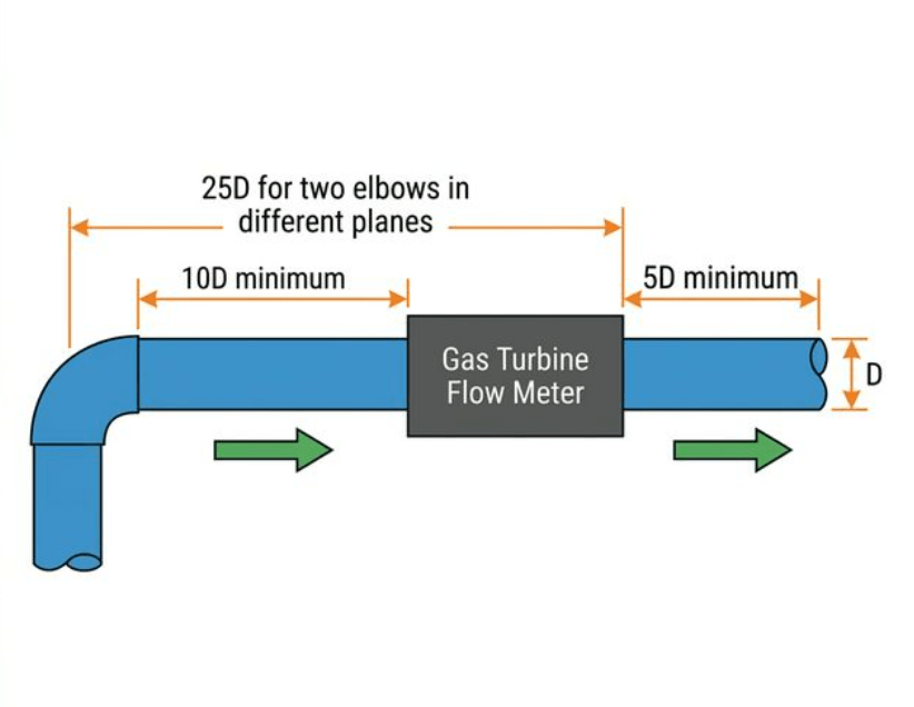
Installation diagram: minimum straight pipe runs required upstream and downstream of a gas turbine flow meter. Upstream disturbances (elbows, valves) create velocity profile distortion that degrades measurement accuracy.
This is where most measurement errors begin. Gas turbine meters measure gas velocity, and any flow disturbance upstream — elbows, valves, expansions — creates asymmetric velocity profiles that corrupt the K-factor.
Standard straight run requirements:
| Upstream Disturbance | Required Upstream | Required Downstream |
|---|---|---|
| Single elbow | 10D | 5D |
| Two elbows (same plane) | 20D | 5D |
| Two elbows (different planes) | 25D | 5D |
| Fully open valve | 20D | 5D |
| Partially open valve | 50D | 5D |
| Reducer/expander | 15D | 5D |
D = nominal pipe diameter. Use flow conditioners if straight piping space is limited.
Deep Dive: Turbine Flow Meter Straight Run Requirement: What’s the Standard?
Orientation and Mounting
Gas turbine meters can be mounted in any orientation. However:
- Horizontal mounting is preferred for wet gas or gas with potential condensate: prevents liquid pooling in the rotor cavity
- Vertical upward flow is acceptable for clean, dry gas
- Vertical downward flow is not recommended — condensate and debris accumulate at the inlet without natural drainage
Upstream Filtration
This is the most overlooked best practice in our field experience.
Natural gas lines frequently carry:
- Compressor oil mist
- Pipeline debris (weld slag, scale)
- Water/condensate droplets
A single particle of weld slag striking the rotor at 20 m/s can permanently alter the K-factor. We recommend installing a 5-micron coalescing filter/separator upstream of every gas turbine flow meter installation. The filter adds a small pressure drop but adds years to rotor bearing life.
Lessons from the Field: The Hidden Cost of Skipping the Filter
A gas distribution company in the Shandong province installed 12 gas turbine meters on a new LNG terminal distribution network. To reduce costs, they skipped the upstream filtration skid.
After 8 months, six of the meters showed K-factor drift exceeding 2% — well outside their custody transfer tolerance. CCTV inspection of the extracted rotors showed microscopic scoring on the blade leading edges from entrained compressor oil particles crystallizing under the rotor’s aerodynamic heating.
Total cost: rotor replacement on 6 units, re-calibration costs, regulatory re-approval of the measurement point, and 3 weeks of production delay. The filtration skid would have cost approximately 15% of the total remediation expense.
Pressure and Temperature Compensation
A gas turbine meter measures volumetric flow at line conditions. For billing and reporting in standard cubic meters (Sm³) or normal cubic meters (Nm³), you must compensate for:
- Working pressure vs. standard pressure (101.325 kPa)
- Working temperature vs. standard temperature (typically 0°C or 15°C)
- Compressibility factor Z (significant at pressures above 0.2 MPa)
Our meters support:
- Integrated PTZ compensation via the onboard LCD display unit
- RS-485 output to an external flow computer (recommended for custody transfer)
- IC card output for prepaid gas metering applications
Common Problems and Troubleshooting
Based on our service history with gas turbine flow meters in natural gas applications:
| Symptom | Likely Cause | Diagnosis | Solution |
|---|---|---|---|
| Flow reading too high | Entrained liquids/droplets in gas stream | Check upstream for condensate | Install/service upstream separator |
| Flow reading too low | Rotor bearing wear, increased friction | Spin rotor by hand — should be free | Replace rotor/bearing cartridge |
| Erratic pulse output | EMI interference on signal cable | Check signal cable shielding | Re-run signal cable away from power cables |
| K-factor drift over time | Rotor blade erosion or deposit buildup | Visual inspection after removal | Clean or replace rotor; install finer filtration |
| No output signal | Power supply failure or pickup coil fault | Check 24VDC supply voltage | Inspect wiring; replace pickup coil |
| Meter won’t start at low flow | Incorrectly sized meter (too large) | Calculate velocity at Qmin | Add bypass valve or upsize line to reduce DN |
| High pressure drop across meter | Partially blocked inlet straighteners | Visual inspection or ΔP measurement | Clean straightener vanes; check filtration |
Full Troubleshooting Reference: Turbine Flow Meter Troubleshooting: How to Fix Common Issues?
Calibration and Maintenance Best Practices
Calibration Intervals
For natural gas custody transfer meters, calibration frequency is typically governed by regulation. Common requirements:
- Annual calibration for custody transfer points
- Biennial calibration for non-billing measurement
- Immediate recalibration after any known process upset (surge, contamination event)
Gas turbine meters can be calibrated in-line using a master meter, or removed for laboratory calibration on a gas flow calibration rig. For high-accuracy custody transfer, we recommend UKAS- or CNAS-accredited laboratory calibration with traceable reference standards.
Per ISO 9951 requirements for turbine meters in gas measurement, calibration should cover at least five flow rates spanning the full operating range.
Routine Maintenance Schedule
| Task | Frequency | Notes |
|---|---|---|
| Visual inspection (external) | Monthly | Check display, housing integrity, signal cable |
| Upstream filter differential pressure check | Monthly | Replace filter element when ΔP exceeds threshold |
| Rotor spin-check (by hand) | Quarterly | Rotor should spin freely with no roughness or clicks |
| Full rotor extraction and inspection | Annually | Check blade condition, bearing wear, deposit buildup |
| Laboratory calibration | Per regulatory requirement | See custody transfer contract specifications |
| Battery voltage check | Semi-annually | Replace lithium battery when display dims |
Calibration Guidance: How Often Do Flow Meters Need To Be Calibrated? and What Do You Need to Know About Flow Meter Calibration?
When to Choose a Gas Turbine Meter vs. Alternatives
Not every natural gas flow meter application is a good fit for turbine technology. Here’s an honest assessment:
| Application | Gas Turbine ✅ | Better Alternative |
|---|---|---|
| Clean dry pipeline gas, custody transfer | ✅ Ideal | — |
| Trade billing with fluctuating demand (20:1) | ✅ DN100+ | — |
| Wet gas / gas with liquid carryover | ❌ Risk | Vortex or ultrasonic |
| Very dirty gas (coal gasification, landfill) | ❌ High wear | Thermal mass or vortex |
| Compressed air monitoring (low precision) | ⚠️ Overkill | Vortex or thermal |
| Bidirectional flow measurement | ❌ Not supported | Ultrasonic |
| Cryogenic LNG (−162°C) | ❌ Beyond temp range | Cryogenic Coriolis |
Flow Meter Technology Comparison: Which Flow Meter Is Best For Natural Gas Measurement?
Applications of Gas Turbine Flow Meters in Natural Gas
Gas turbine meters are widely deployed across the natural gas value chain as versatile measurement solutions:
| Application | Why Turbine Meter |
|---|---|
| City Gate Stations | Custody transfer from transmission to distribution network |
| Industrial Burner Control | Accurate fuel monitoring for boilers, furnaces, kilns |
| CNG Filling Stations | High-pressure dispenser metering, fast-fill accuracy |
| Power Plant Fuel Gas | Gas turbine generator fuel consumption monitoring |
| LNG Off-take Metering | Regasified LNG volume measurement |
| Gas Sub-metering | Multi-building or multi-process allocation metering |
| Process Control | Reactor feed gas, combustion stoichiometry control |
For each application, the measurement solutions approach differs slightly. City gate custody transfer demands accredited calibration and an approved flow computer. CNG filling stations require high-frequency pulse output compatible with dispenser electronics. Always communicate the specific application to your meter supplier.
Frequently Asked Questions
What accuracy can I expect from a gas turbine flow meter for natural gas?
Soaring Instrument gas turbine flow meters achieve ±1.5%R as standard, improving to ±1.0%R after individual calibration on our gas test bench. Larger diameters (DN100 and above) achieve better accuracy because the rotor-to-pipe-diameter ratio improves and boundary-layer effects are reduced. For custody transfer, we recommend requesting calibration documentation covering five flow points across the declared operating range.
How does gas composition affect gas turbine meter accuracy?
Gas turbine flow meters measure volumetric flow rate at line conditions regardless of gas composition. Composition matters when you convert working volume to standard/normal volume: different compositions have different compressibility factor (Z) values. If your gas composition varies significantly — for example, if you measure both pipeline natural gas and LPG-air mixture — the volume corrector must be programmed with the correct gas composition data to avoid systematic errors in the standard volume calculation.
What straight piping length is required upstream of a gas turbine flow meter?
The minimum requirement for a single upstream elbow is 10 pipe diameters (10D) of straight pipe. Two elbows in different planes require 25D. Partially open control valves — the most common field problem — require 50D upstream. If physical space doesn’t permit these runs, use a flow conditioner (tube bundle type), which typically reduces requirements to 5D. Always verify the conditioner is compatible with your specific meter design.
Can gas turbine flow meters handle high-pressure natural gas?
Yes. Gas turbine flow meters are available in a wide variety of pressure ratings — contact our factory for the specific maximum working pressure appropriate to your application. At higher line pressures, gas density increases significantly, which benefits turbine meter performance: the rotor receives more angular momentum per revolution, improving low-flow sensitivity and extending the effective turndown ratio. The Engineering ToolBox provides useful reference data on natural gas properties at different pressures and temperatures helpful for pre-sizing calculations.
What is the typical service life of a gas turbine flow meter?
With clean, dry gas and proper upstream filtration, rotor bearings typically last 5–8 years before requiring replacement. The meter body and electronics can operate for 15–20 years. The most common service items are the rotor cartridge and the battery pack (for battery-powered configurations). We maintain a spare parts program for all current models.
How do I commission a gas turbine flow meter on a new natural gas line?
Key commissioning steps in our field protocol:
- Blow-down the piping before installing the meter — remove all construction debris, rust, and liquid from the line
- Install with temporary bypass to allow commissioning flow without full process flow
- Verify power supply — confirm 24VDC nominal and stable
- Program flow computer — enter pipe ID, K-factor, gas composition, reference conditions
- Verify pulse output — compare meter totaliser against a reference master meter or calibrated transfer prover
- Seal the parameter access for custody transfer applications (anti-tamper sealing per local regulation)
Is a gas turbine flow meter suitable for biogas or biomethane measurement?
It depends on the gas conditioning quality. Biogas and biomethane often contain traces of hydrogen sulfide (H₂S) and moisture. H₂S can be corrosive to certain bearing materials and internal components. We recommend contacting our factory team to discuss material compatibility for your specific biogas composition before specifying. Upstream gas conditioning (drying, H₂S scrubbing) is strongly recommended to protect the meter and extend service life.
Conclusion: The 5 Best Practices That Matter Most
Based on hundreds of gas turbine flow meter installations in natural gas measurement applications, these five practices separate reliable, long-term performers from problem installations:
Size for the actual flow range, not the pipe size. Calculate velocity at Qmax and Qmin. Use DN100+ for applications requiring 20:1 turndown.
Install upstream filtration — always. A 5-micron coalescing filter/separator is the single most cost-effective protection for gas turbine meter reliability. The rotor is precise but not indestructible.
Meet straight piping requirements — or use a flow conditioner. Ten pipe diameters minimum upstream. Don’t compromise on this; the measurement errors caused by distorted velocity profiles are systematic and hard to detect without a reference meter.
Apply temperature and pressure compensation for standard volume output. Raw volumetric flow at line conditions is not useful for billing or regulatory reporting. Integrate a volume corrector or flow computer from day one.
Calibrate on gas, not on water. Water calibration of a gas turbine meter introduces rotor drag differences that don’t represent actual gas performance. For custody transfer accuracy, insist on gas calibration from an accredited laboratory.
Contact Soaring Instrument
Our engineering team supports gas turbine flow meter sizing, application review, and installation design for natural gas measurement projects worldwide. Whether you’re commissioning a new city gate station or optimizing an existing industrial measurement point, we can help select and configure the right measurement solutions for your specific flow range, pressure, and accuracy requirements.
Request a Free Application Review | View Gas Turbine Flow Meter Specifications
Related Articles
- Turbine Flow Meter Working Principle: How Does It Operate?
- Turbine Flow Meter Straight Run Requirement: What’s the Standard?
- Turbine Flow Meter Troubleshooting: How to Fix Common Issues?
- Understanding Turbine Flow Meter Turndown Ratio: Why Is It Critical?
- Which Flow Meter Is Best For Natural Gas Measurement?
- How Do Turbine and Electromagnetic Flow Meters Compare?
- What Flow Meter Types Are Best Suited for Oil and Gas Industry Applications?