Proper installation ensures accurate readings and long service life. Many measurement problems stem from ignoring basic installation principles.
For optimal performance: 1) Always install in fully filled pipes, 2) Maintain 10 pipe diameters of straight run upstream (5 downstream), 3) Ground properly, 4) Avoid high points and direct sunlight, and 5) Orient based on fluid type – vertical upward flow for liquids with solids, horizontal for clean liquids.
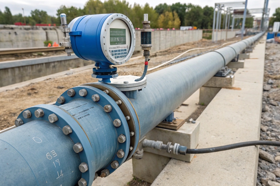
Proper Electromagnetic Flow Meter Installation
Having installed thousands of these meters worldwide, I’ve identified these critical guidelines.
What Is the Rule of Thumb for Magnetic Flow Meter Installation?
Simple principles prevent most common problems.
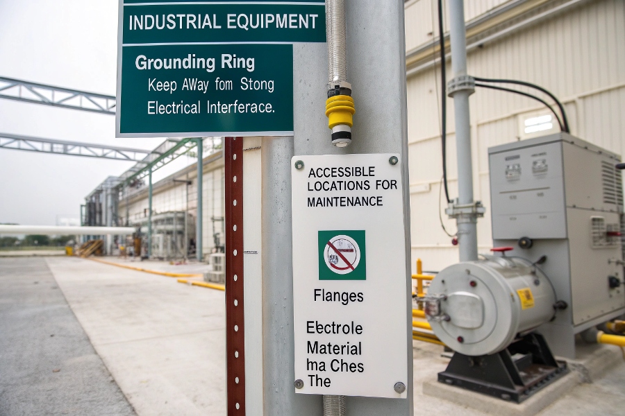
Basic rules: 1) Ensure continuous conductivity (grounding ring if needed), 2) Keep away from strong electrical interference1, 3) Install in accessible locations for maintenance, 4) Match electrode material to fluid, 5) Use proper supports to avoid stress on flanges.
Electromagnetic Flow Meter Installation Basics
These fundamentals apply to all installations:
Essential Installation Checklist
| Requirement | Minimum Standard | Consequences if Ignored |
|---|---|---|
| Pipe Fill | 100% full at all times | Measurement errors up to 100% |
| Straight Pipe Runs | 10D upstream, 5D downstream | Flow profile distortion |
| Grounding | Dedicated ground rod recommended | Electrical noise interference |
| Electrode Alignment | Horizontal in most cases | Air bubble accumulation |
| Support | Proper pipe hangers/supports | Mechanical stress on meter |
| Environment | Protected from extreme weather | Electronics damage over time |
How Should a Flow Meter Be Installed?
Step-by-step installation ensures reliable operation.
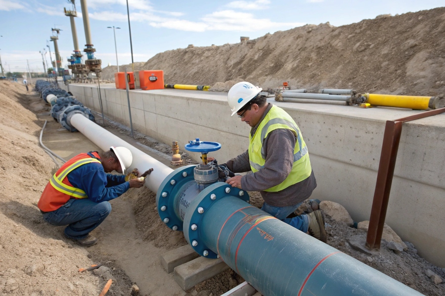
Key steps: 1) Verify pipe size/material match, 2) Install isolation valves2, 3) Check flow direction matches meter marking, 4) Torque flange bolts evenly, 5) Ground properly (10AWG minimum), 6) Program parameters before startup, 7) Verify zero reading with full pipe/no flow.
Flow Meter Installation Steps
Follow this sequence carefully:
Installation Procedure
-
Site Preparation
- Clear work area
- Have proper tools ready (torque wrench, grounding kit)
- Verify pipe conditions (clean, round)
-
Pre-Installation Checks
- Match meter size to pipe (DN rating)
- Verify fluid compatibility (electrodes/liner)
- Check calibration certificate
-
Physical Installation
- Install with proper alignment (no pipe stress)
- Use gaskets specified by manufacturer
- Torque bolts in star pattern (follow specs)
-
Electrical Connections
- Run shielded cable in separate conduit
- Ground to earth (≤5 ohms resistance)
- Protect cables from moisture
-
Commissioning
- Purge air from system
- Check for leaks
- Verify zero under no-flow condition
What Are the Requirements for a Magnetic Flow Meter?
Meeting technical specifications prevents failures.
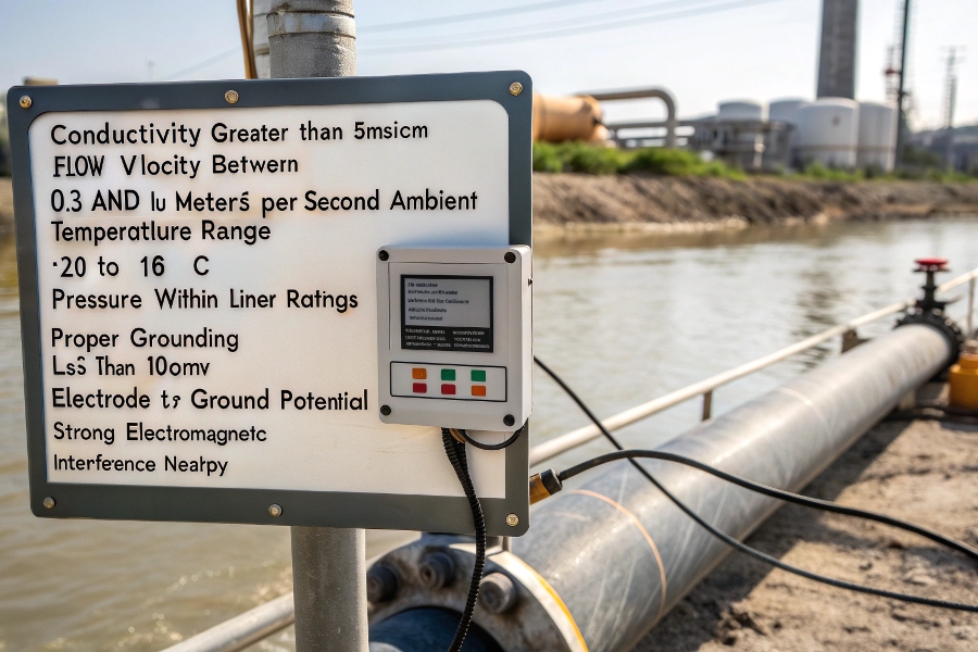
Critical requirements: 1) Conductivity >5μS/cm, 2) Flow velocity 0.3-10 m/s, 3) Ambient temperature -20 to +60°C, 4) Pressure within liner rating, 5) Proper grounding (<100mV electrode-to-ground potential), 6) No strong electromagnetic interference nearby.
Magnetic Flow Meter Requirement
These specifications affect performance:
Operational Requirements Table
| Parameter | Minimum Requirement | Maximum Limit | Measurement Impact |
|---|---|---|---|
| Fluid Conductivity | 5 μS/cm | None | Below 5μS = no measurement |
| Flow Velocity | 0.3 m/s | 10 m/s | Low velocity = unstable |
| Temperature | -20°C (special models) | +180°C (PTFE liner) | Beyond limits damages liner |
| Pressure | Full vacuum | 100 bar (depends) | Exceeding bursts liner |
| Pipe Size | DN2 (tiny bore) | DN3000 (large) | Proper sizing crucial |
| Straight Pipe | 10D upstream | 5D downstream | Less causes profile distortion |
What Is the Preferred Orientation to Use When Installing a Magnetic Flowmeter?
Orientation significantly affects measurement quality.
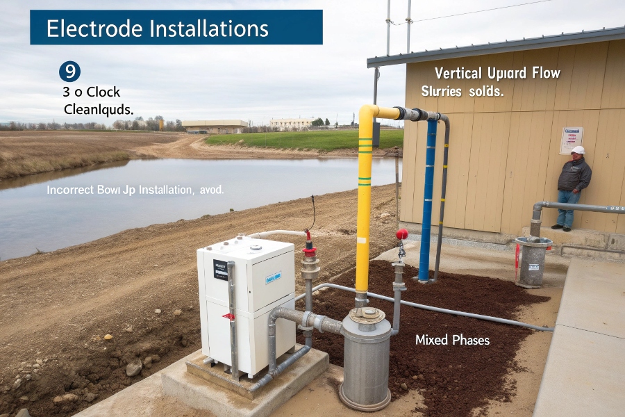
Best practices: 1) Horizontal installation (electrodes at 9/3 o’clock) for clean liquids, 2) Vertical upward flow for slurry/solids, 3) Never install bowl-up, 4) Avoid top-of-pipe installation where air collects, 5) For mixed phases, orient to keep electrodes clean.
Flow Meter Orientation Guidelines
Different orientations serve different purposes:
Orientation Guide
| Application | Recommended Orientation | Why? | Avoid |
|---|---|---|---|
| Clean liquids3 | Horizontal (9/3 o’clock) | Prevents electrode coating | Top mounting (12 o’clock) |
| Slurries/solids4 | Vertical upward flow | Keeps electrodes clean | Vertical downward |
| Gas-entrained5 | 45° upward angle | Allows gas to escape | Any flat orientation |
| High temperature | Horiz. or vert. upward | Prevents liner damage | Bowl-down positions |
| Viscous fluids | Vertical upward | Prevents settling | Horizontal mounting |
Conclusion
Proper electromagnetic flow meter installation demands attention to orientation, grounding, pipe conditions and environmental factors. Following these guidelines ensures accurate, reliable measurements and maximizes the meter’s lifespan. Always consult manufacturer specifications for your specific model before installation.
-
Learning about interference mitigation techniques can significantly improve the performance of your flow measurement systems. ↩
-
Understanding the proper installation of isolation valves is crucial for ensuring system reliability and safety. Explore this resource for expert insights. ↩
-
Understanding the optimal orientation for clean liquids can enhance measurement accuracy and prolong equipment life. ↩
-
Exploring this topic can help you maintain clean electrodes and improve the efficiency of your processes. ↩
-
Learning about this orientation can help you effectively manage gas escape and improve system performance. ↩