Struggling to find accurate flow measurement solutions for small diameter pipes? You’re not alone—87% of engineers report challenges when measuring flow in pipes below DN50.
Quick Answer: Small pipe ultrasonic flow meters (DN10-DN40) use transit-time technology with specialized compact transducers to measure liquid flow rates from 1-400 LPM without cutting pipes. Modern clamp-on designs like the SR7 series achieve <2% FS accuracy with 0.5-second response times, making them ideal for chemical dosing, pharmaceutical processes, and HVAC applications.
For a broader understanding of ultrasonic flow measurement technology, see our Complete Guide to Ultrasonic Flow Meters.
What Is a Small Pipe Ultrasonic Flow Meter?
A small pipe ultrasonic flow meter is a specialized instrument designed for accurate flow measurement in pipes with diameters from DN10 (⅜") to DN40 (1½"). Unlike standard ultrasonic meters designed for larger pipes, these devices feature compact transducers, optimized signal processing, and higher frequency operation to overcome the unique challenges of small diameter measurement.
Why Small Pipes Are Challenging
In our field experience installing hundreds of flow meters, we’ve identified three core challenges unique to small pipe applications:
| Challenge | Cause | Impact on Measurement |
|---|---|---|
| Limited Acoustic Path | Shorter signal travel distance | Reduced signal-to-noise ratio |
| Sensitive Flow Profile | Higher surface-to-volume ratio | Greater wall effects on flow |
| Mounting Constraints | Limited physical space | Alignment and coupling difficulties |
| Reynolds Number Effects | Lower flow velocities typical | Laminar/transition flow complications |
Key Insight from the Field: During a recent pharmaceutical plant installation, we discovered that conventional ultrasonic meters designed for DN50+ pipes showed 8-12% measurement errors when adapted for DN25 applications. Purpose-built small pipe meters reduced this error to under 2%.
How Does Transit-Time Technology Work in Small Pipes?
Small pipe ultrasonic flow meters primarily use transit-time measurement, which calculates flow velocity by measuring the time difference between ultrasonic signals traveling upstream and downstream. This principle is based on the Doppler effect and acoustic physics well-documented in flow metering standards such as ISO 12242:2012 for ultrasonic flow measurement.
The Transit-Time Principle
The fundamental formula for flow calculation:
Flow Velocity (V) = (L × ΔT) / (2 × T₁ × T₂ × cos θ)
Where:
- L = Acoustic path length
- ΔT = Time difference (downstream vs. upstream)
- T₁, T₂ = Transit times
- θ = Beam angle
In small pipes, this presents unique considerations:
- Higher Transducer Frequencies (1-5 MHz) – Required for adequate signal resolution in confined spaces
- Optimized Beam Angles (30°-55°) – Compensates for short acoustic paths
- Advanced Signal Processing – Filters noise and enhances weak signals
The speed of sound in water varies with temperature (approximately 1,497 m/s at 25°C), which is why temperature compensation is critical for accurate measurements. Reference values can be found at Engineering ToolBox – Speed of Sound in Water.
Small Pipe vs. Large Pipe Measurement Comparison
| Parameter | Large Pipe (>DN100) | Small Pipe (DN10-DN40) |
|---|---|---|
| Transducer Frequency | 0.5-1 MHz | 1-5 MHz |
| Signal Path Type | Multi-path possible | Single-path optimized |
| Minimum Velocity | 0.03 m/s | 0.15 m/s |
| Typical Accuracy | ±0.5% of reading | ±2% of full scale |
| Installation Sensitivity | Moderate | High |
For more details on transit-time technology, explore How Does a Transit-Time Ultrasonic Flow Meter Work?
Types of Small Pipe Ultrasonic Flow Meters
1. Clamp-On (External) Type
Best For: Non-invasive installation, retrofit applications, corrosive media
Clamp-on transducers mount externally on the pipe surface, making them ideal when:
- Process cannot be interrupted
- Media is corrosive or pure (no contamination risk)
- Temporary or portable measurement is needed
Advantages:
- Zero pressure drop
- No pipe cutting required
- Suitable for hazardous media
- Easy relocation
Limitations:
- Requires good pipe surface condition
- Wall thickness limitations
- Slightly lower accuracy than inline types
Learn more about clamp-on applications: Can Clamp-On Ultrasonic Flow Meters Work Effectively on Small Pipes?
2. Inline (Wetted) Type
Best For: Maximum accuracy, permanent installations, custody transfer
Inline meters place transducers in direct contact with the fluid through spools or insertion fittings.
Advantages:
- Higher accuracy (±0.5%)
- No wall thickness dependency
- Better signal strength
Limitations:
- Requires pipe modification
- Process interruption for installation
- Pressure drop considerations
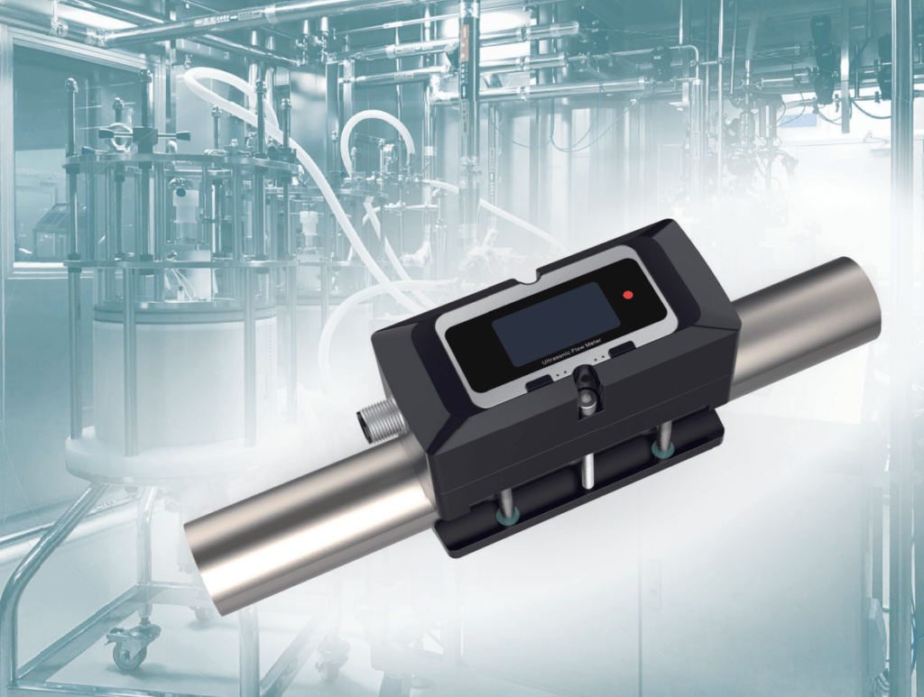
3. Integrated Clamp-On (All-in-One) Design
Modern solutions like the SR7 series integrate the transducer and electronics into a single compact unit:
| Feature | Traditional | SR7 Integrated |
|---|---|---|
| Components | Separate transducer + transmitter | Single unit |
| Installation Time | 30-60 minutes | 3-5 minutes |
| Setup Steps | 10+ parameters | 2 parameters (OD + Wall Thickness) |
| Cable Management | Complex | Minimal |
SR7 Small Pipe Ultrasonic Flow Meter: Technical Specifications
Based on our SR7 product line specifically designed for small pipes, here are the detailed specifications:
Performance Specifications
| Parameter | Specification | Notes |
|---|---|---|
| Pipe Size Range | DN10, DN15, DN20, DN25, DN32, DN40 | OD range: 12mm – 52mm |
| Accuracy | <2% FS (Standard) / <3% FS (Corrosion Resistant) | Under normal conditions |
| Response Time | 0.5 – 3 seconds | Configurable via damping |
| Flow Velocity Range | 0.15 – 10 m/s | Low-cut adjustable |
| Repeatability | 0.2% of reading | At stable flow conditions |
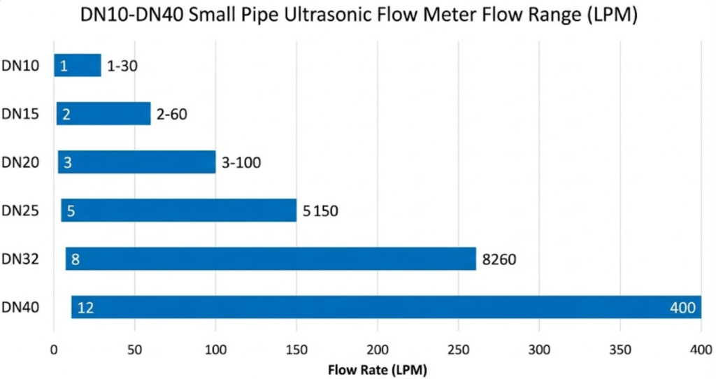
Flow Range by Pipe Size
| Pipe Size (DN) | External Diameter Range | Flow Range (LPM) |
|---|---|---|
| DN10 | Ø12mm – Ø18mm | 1 – 30 |
| DN15 | Ø18mm – Ø23mm | 2 – 60 |
| DN20 | Ø23mm – Ø28mm | 3 – 100 |
| DN25 | Ø28mm – Ø33mm | 5 – 150 |
| DN32 | Ø33mm – Ø44mm | 8 – 260 |
| DN40 | Ø44mm – Ø52mm | 12 – 400 |
Environmental & Electrical Specifications
| Parameter | Standard Version | Medium-Temp Version |
|---|---|---|
| Media Temperature | -10°C to 65°C | -10°C to 105°C |
| Ambient Temperature | -10°C to 60°C | -10°C to 60°C |
| Power Supply | 20-28V DC | 20-28V DC |
| Power Consumption | 1W | 1W |
| Protection Rating | IP54 | IP54 |
| Display | 1.5" OLED | 1.5" OLED |
Compatible Pipe Materials
- Metal Pipes: Stainless steel, Carbon steel, Copper
- Plastic Pipes: PVC, PP, PE, PVDF (rigid pipes only)
Note: For other materials, contact our technical team to verify acoustic compatibility.
Installation Guide: Getting It Right the First Time
Straight Run Requirements
Proper installation location is critical for accuracy. Based on our extensive field experience:
| Upstream Condition | Upstream Requirement | Downstream Requirement |
|---|---|---|
| Standard installation | >10D | >5D |
| After elbow | >10D | >5D |
| After valve | >30D | >10D |
| After pipe reduction | >10D | >5D |
| After pipe expansion | >30D | >5D |
| After pump | >20D | >10D |
D = Pipe internal diameter
For complete installation guidelines, see Pipe Requirements for Ultrasonic Flow Meter Installation.
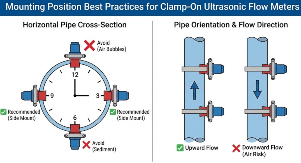
Mounting Position Best Practices
Recommended Positions:
- ✅ 3 o’clock or 9 o’clock on horizontal pipes (transducers on sides)
- ✅ Vertical pipes with upward flow
- ✅ Ascending horizontal sections
Avoid:
- ❌ Top of horizontal pipe (air bubble accumulation)
- ❌ Bottom of horizontal pipe (sediment accumulation)
- ❌ Vertical pipes with downward flow (air entrainment risk)
The Two-Step Setup Process (SR7)
One of the most significant advantages of integrated designs like the SR7 is the simplified setup:
Step 1: Enter Outer Diameter (OD)
Configure the exact external diameter measurement of your pipe within the supported range.
Step 2: Enter Wall Thickness (THK)
Input the pipe wall thickness (supported: 1.0mm – 5.5mm in 0.5mm increments).
Important: The calculated inner diameter must not fall below the DN specification minimum. For example, DN10 requires a calculated ID ≥ 10mm.
Lessons from the Field: Common Installation Mistakes
Case Study 1: Pharmaceutical Water System (DN25)
Problem: Initial readings showed ±15% deviation from reference meter.
Root Cause: Meter installed only 3D downstream of a 90° elbow (should be >10D).
Solution: Relocated meter to achieve 12D straight run upstream. Deviation reduced to <1.5%.
Case Study 2: Chemical Dosing Line (DN15)
Problem: Intermittent "No Signal" errors.
Root Cause: Air bubbles trapped at transducer location (top-mounted on horizontal pipe).
Solution: Rotated meter to 3 o’clock position. Continuous stable readings achieved.
Wiring and Output Configuration
M12-A Connector Pinout
Based on the SR7 product manual, the wiring definition is:
| Wire Color | Function | Notes |
|---|---|---|
| Brown | DC+ (Power in +) | 24VDC power positive |
| Black | 4-20mA OUT+ | Flow 4-20mA output positive |
| Blue | 0V / DC- / 4-20mA OUT- | Power negative / 4-20mA common |
| White | RS485 A | Modbus communication A |
| Grey | RS485 B | Modbus communication B |
Available Output Options
| Output Type | Application | Configuration |
|---|---|---|
| 4-20mA | PLC/DCS integration | Proportional to flow rate |
| RS485 Modbus | SCADA/BMS systems | RTU protocol |
| OCT (Pulse) | Totalizer integration | 0-5KHz frequency output |
| Relay | Alarm/batch control | High/low limit triggers |
For detailed Modbus register mapping, refer to our SR7 Technical Manual.
Applications: Where Small Pipe Flow Meters Excel
1. Chemical Injection & Dosing Systems
Small pipe ultrasonic meters are ideal for monitoring precise chemical dosing:
- Corrosion inhibitor injection
- pH adjustment chemicals
- Coagulant/flocculant dosing
- Biocide treatment systems
Key Advantage: Non-invasive measurement prevents contamination and eliminates pressure drop in precision dosing circuits.
2. Pharmaceutical & Biotech
Clean-in-place (CIP) systems and process water monitoring:
- DI water distribution
- Buffer solution preparation
- Purified water loops
- Small-scale batch processing
For pharmaceutical water applications, see What Makes Ultrasonic Flow Meters Ideal for Water Measurement?
3. HVAC & Building Systems
- Chilled water submetering
- Fan coil unit monitoring
- Heat transfer fluid measurement
- Cooling system optimization
Related reading: How Do Clamp-On Ultrasonic Flow Meters Measure Energy in Different Applications?
4. Laboratory & Research
- Pilot plant studies
- Flow characterization
- Equipment testing
- Calibration verification
5. Food & Beverage
- Flavor/additive injection
- CIP monitoring
- Small-batch ingredients
- Sanitary processing lines
See also: Brewing & Dairy: How Food-Grade EMFs Prevent Contamination
6. Oil & Gas Industry
Small pipe ultrasonic meters serve critical roles in oil and gas applications:
- Chemical injection systems – Monitoring corrosion inhibitors, scale inhibitors, and demulsifiers
- Hydraulic control lines – Subsea and topside umbilical monitoring
- Sampling systems – Process sample line flow verification
- Pilot plant testing – Refinery process optimization studies
- Fuel oil systems – Burner feed monitoring
Field Note: In offshore platform chemical injection applications, we’ve seen 30-40% improvement in chemical efficiency by implementing accurate small pipe flow measurement. Previously, operators were overdosing due to lack of real-time monitoring.
For more oil and gas applications, see What Flow Meter Types Are Best Suited for Oil and Gas Industry Applications?
Troubleshooting Common Issues
Problem-Cause-Solution Matrix
| Problem | Possible Cause | Solution |
|---|---|---|
| No signal (Q=0) | Air in pipe | Verify full pipe condition |
| Poor coupling | Apply couplant gel, check surface | |
| Incorrect parameters | Verify OD and wall thickness settings | |
| Unstable readings | Turbulent flow | Increase damping setting |
| Pump pulsation | Install pulsation dampener upstream | |
| Air bubbles | Relocate to 3 o’clock position | |
| Consistently high/low readings | Incorrect pipe size | Re-measure OD and wall thickness |
| Scale/deposit on pipe | Clean pipe surface | |
| Wrong flow direction | Check DIR parameter setting | |
| Signal strength low | Thick pipe wall | Increase AMP (gain) setting |
| Corroded pipe | Consider inline meter option | |
| Low velocity | Verify above 0.15 m/s minimum |
Zero Point Calibration
Critical: Zero calibration must be performed with the pipe completely full and zero flow (static) conditions:
- Close upstream and downstream valves
- Wait 5+ minutes for fluid to settle
- Access Zero menu (Zero setting)
- Confirm zero point capture
This removes any static offset and dramatically improves low-flow accuracy.
For additional troubleshooting guidance: Why Is My Ultrasonic Flow Meter Not Working? Expert Solutions
Selection Guide: Choosing the Right Small Pipe Flow Meter
Decision Framework
Step 1: Determine Pipe Size
Measure actual external diameter and wall thickness. Select the appropriate DN model.
Step 2: Evaluate Media Properties
- Temperature range (Standard: -10°C to 65°C / Medium-temp: -10°C to 105°C)
- Conductivity (ultrasonic works with non-conductive fluids)
- Particle content (transit-time requires <50 ppm solids)
Step 3: Consider Installation Environment
- Corrosive atmosphere? (Select corrosion-resistant version with plastic hardware)
- Vibration present? (May require damping adjustments)
- Outdoor exposure? (Ensure IP rating adequate)
Step 4: Define Output Requirements
- Analog integration → Select 4-20mA
- Digital communication → Select RS485 Modbus
- Pulse totalization → Select OCT output
- Alarm functions → Select Relay option
SR7 Model Selection Code
Format: SR7-[Pipe]-[Temp]-[Outputs]-[Options]
| Code | Meaning |
|---|---|
| Pipe Size: 10A, 15A, 20A, 25A, 32A, 40A | DN10-DN40 options |
| Temperature: TT02S (Standard), TT03S (Medium) | -10°C to 65°C / 105°C |
| Outputs: A (4-20mA), M (Modbus), O (OCT), R (Relay) | Select 2 of 4 |
| Options: T (Temperature display) | Optional feature |
Example: SR7-20A-TT02S-AM = DN20, Standard temp, 4-20mA + Modbus outputs
Small Pipe Flow Meters vs. Alternative Technologies
Technology Comparison for DN10-DN40 Applications
| Feature | Ultrasonic (Transit-Time) | Electromagnetic | Turbine | Coriolis |
|---|---|---|---|---|
| Non-conductive fluids | ✅ Yes | ❌ No | ✅ Yes | ✅ Yes |
| No pressure drop | ✅ Yes (clamp-on) | ⚠️ Minimal | ❌ No | ⚠️ Minimal |
| No moving parts | ✅ Yes | ✅ Yes | ❌ No | ✅ Yes |
| Small pipe accuracy | Good (±2% FS) | Good (±0.5%) | Poor | Excellent (±0.1%) |
| Installation ease | ⭐⭐⭐⭐⭐ | ⭐⭐⭐ | ⭐⭐ | ⭐⭐ |
| Cost | $$ | $$$ | $ | $$$$ |
For a detailed comparison: EMF vs. Ultrasonic vs. Coriolis Flowmeters: Which Wins for Your Industry?
FAQ: Small Pipe Ultrasonic Flow Meters
What is the minimum pipe size for ultrasonic flow meters?
Modern small pipe ultrasonic meters can measure pipes as small as DN10 (⅜" / OD 12mm). Some specialized laboratory units work down to DN6 or DN8, though these typically require custom calibration. The SR7 series supports DN10-DN40 as standard.
Can ultrasonic flow meters measure non-conductive liquids?
Yes. This is a key advantage over electromagnetic flow meters. Ultrasonic transit-time technology works with any homogeneous liquid regardless of conductivity, including:
- Deionized (DI) water
- Oils and hydrocarbons
- Alcohols and solvents
- Chemical solutions
What is the accuracy of small pipe ultrasonic meters?
Typical accuracy for small pipe clamp-on ultrasonic meters is ±2% of full scale under optimal conditions. Factors affecting accuracy include:
- Installation quality (straight run, mounting position)
- Flow velocity (best above 0.3 m/s)
- Pipe condition (scale, corrosion)
- Proper parameter setup
For higher accuracy requirements (±0.5%), consider inline wetted meters.
Do small pipe ultrasonic meters work with plastic pipes?
Yes, with limitations. Compatible plastic materials include:
- PVC (Polyvinyl Chloride)
- PP (Polypropylene)
- PE (Polyethylene)
- PVDF (Polyvinylidene Fluoride)
Requirements:
- Pipe must be rigid (not flexible tubing)
- Wall thickness within supported range (typically 1.0-5.5mm)
- Homogeneous material (not reinforced/composite)
How often do small pipe ultrasonic meters need calibration?
For most industrial applications, annual calibration verification is recommended. However:
- Critical processes: Semi-annual verification
- Custody transfer: Per regulatory requirements (often annual with documentation)
- Stable, non-critical monitoring: Every 2-3 years may be acceptable
The non-invasive nature of clamp-on meters means they experience minimal drift compared to wetted sensors.
What maintenance is required?
Small pipe clamp-on ultrasonic meters require minimal maintenance:
- Periodic visual inspection of transducer mounting
- Check cable connections
- Verify display readings against process expectations
- Clean pipe surface if access allows (during shutdowns)
- No moving parts to replace
For calibration verification procedures, reference standards such as those published by NIST (National Institute of Standards and Technology) provide guidance on measurement traceability.
See also: What’s the Best Way to Maintain Your Ultrasonic Flow Meter?
Conclusion: Key Takeaways
Purpose-built small pipe meters outperform adapted large-pipe units — specialized transducers and signal processing are essential for DN10-DN40 accuracy.
Clamp-on technology offers the fastest ROI — zero downtime installation, no pressure drop, and no contamination risk make it ideal for most applications.
Installation quality determines measurement quality — respect straight run requirements and mounting position guidelines for best results.
The SR7 integrated design simplifies deployment — only two setup parameters (OD and wall thickness) are needed versus 10+ for conventional systems.
Consider your complete application requirements — temperature range, output needs, and environmental conditions should guide model selection.
Need Expert Assistance?
Our flow measurement specialists have helped hundreds of facilities optimize small pipe flow measurement. Whether you’re designing a new system or troubleshooting an existing installation, we’re here to help.
Request a Quote or Technical Consultation →
Explore Our Small Pipe Solutions:
Related Articles
- The Complete Guide of Ultrasonic Flow Meter
- Can Clamp-On Ultrasonic Flow Meters Work Effectively on Small Pipes?
- Precision Matters: The Role of Ultrasonic Flow Meters in Small Pipe Applications
- Why Do 87% of Engineers Need Customized Ultrasonic Flow Meters for Small Pipes?
- How to Install a Transit Time Ultrasonic Flow Meter Correctly?
- What Are the Key Differences Between Inline and Clamp-On Ultrasonic Flow Meters?
Last Updated: January 2026 | Shanghai Soaring Instrument Technology Co., Ltd.