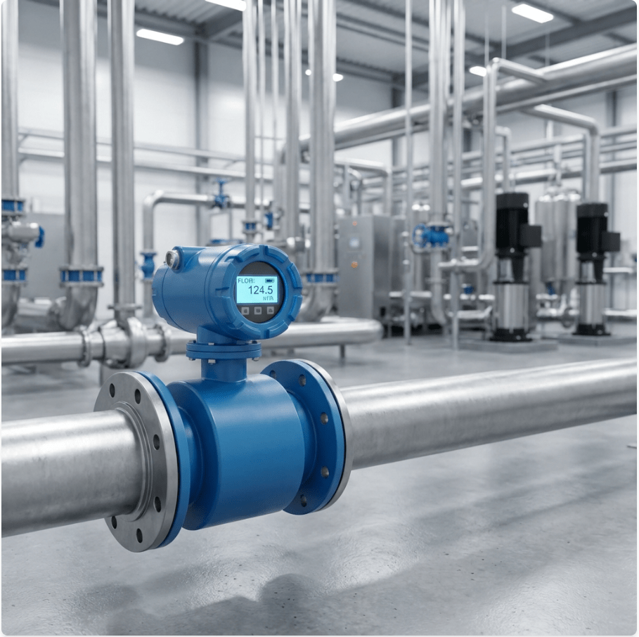
A magnetic flow meter (also known as a magmeter or electromagnetic flow meter) is a precision volumetric flow measurement device designed for conductive liquids in closed pipes.
Distinguished by its obstruction-free design, the magnetic flow meter creates virtually no additional pressure drop and contains no moving parts to wear out. It is the industry standard for measuring challenging fluids—from corrosive acids and high-pressure drilling mud to abrasive mining slurries and municipal wastewater.
This guide provides a rigorous technical overview of magnetic flow meter technology, including its operating principle, product configurations, material selection, installation requirements, and industrial applications—based on Soaring Instrument’s complete electromagnetic flow meter product line.
How Does a Magnetic Flow Meter Work?
Magnetic flow meters operate based on Faraday’s Law of Electromagnetic Induction, discovered by Michael Faraday in 1831. This law states that when a conductor moves through a magnetic field, a voltage is induced perpendicular to both the direction of motion and the magnetic field.
The Measurement Principle
In a magnetic flow meter, the conductive liquid serves as the moving conductor. As the fluid flows through the magnetic field generated by the meter’s coils, a voltage is induced across the fluid. This voltage is detected by electrodes mounted on opposite sides of the pipe wall.
The induced voltage follows the equation:
U = B × D × v̄
Where:
U = Induced voltage (mV)
B = Magnetic flux density (T, Tesla)
D = Internal pipe diameter / electrode spacing (m)
v̄ = Mean flow velocity (m/s)
Since B and D are fixed constants for a given sensor, the induced voltage U is directly proportional to the fluid velocity v̄. This linear relationship ensures consistent accuracy across the full measurement range, unaffected by changes in fluid density, viscosity, or temperature.
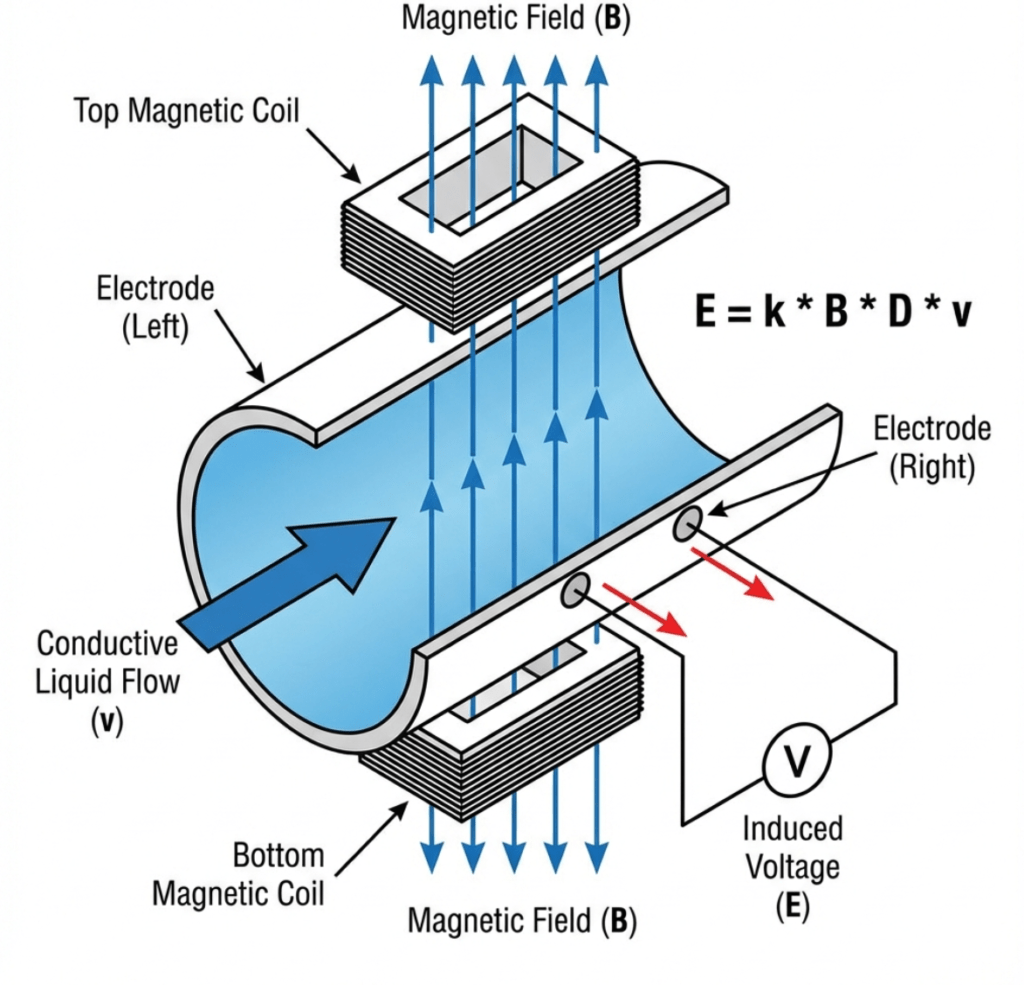
Figure 1: Working Principle of Magnetic Flow Meter (Faraday’s Law of Induction)
📘 Technical Deep Dive: How Electromagnetic Flowmeters Work: Faraday’s Law in Action
Modern Excitation Technology
Soaring Instrument electromagnetic flow meters utilize low-frequency square wave (pulsed DC) excitation, which provides:
Stable zero point with low power consumption
High accuracy measurement
Excellent noise rejection in industrial environments
Response speed ≤ 1 second
Product Configurations
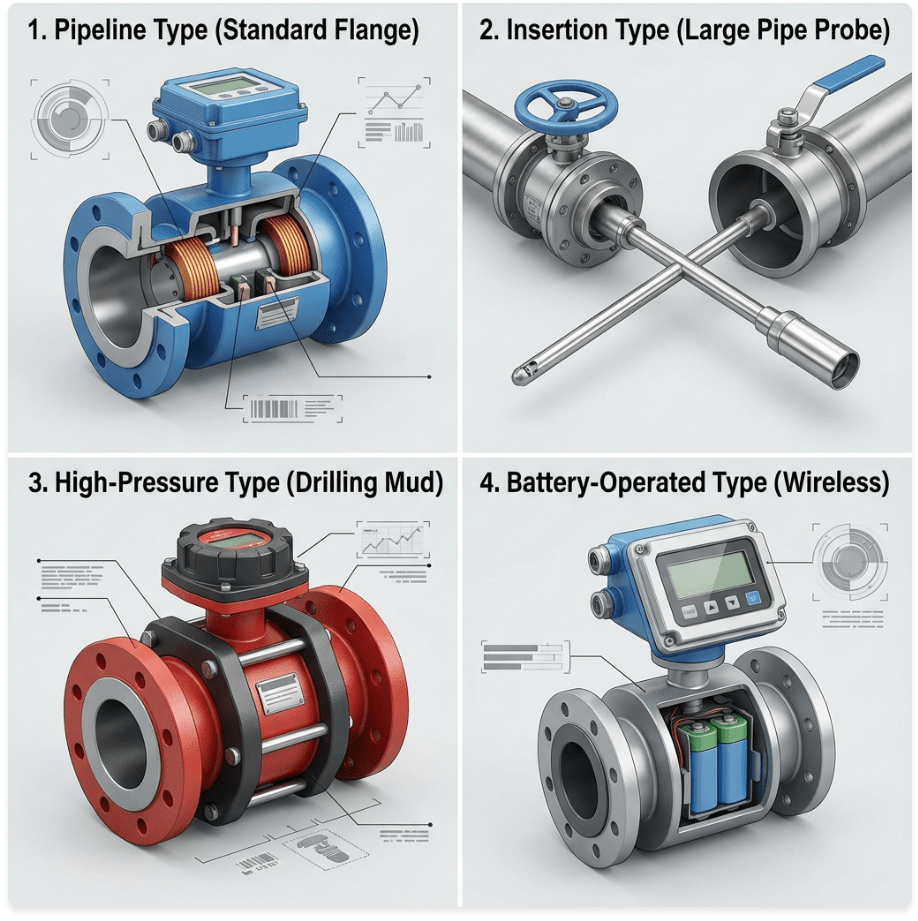
Figure 2: Soaring Instrument Magnetic Flow Meter Product Family
A complete range of electromagnetic flow meters is available to match virtually any application requirement:
1. Pipeline Type (Inline) Electromagnetic Flow Meter
The standard configuration for most industrial applications.
| Parameter | Specification |
|---|---|
| Nominal Diameter | DN3 – DN3000 |
| Accuracy | ±0.5% of reading |
| Minimum Conductivity | ≥ 5 μS/cm |
| Medium Temperature | -40°C to +180°C |
| Ambient Temperature | -10°C to +60°C |
| Working Pressure | Up to 4.0 MPa (Standard); up to 42 MPa (High-pressure option) |
| Velocity Range | 0.1 – 15 m/s |
| Turndown Ratio | 150:1 |
| Process Connection | Flange, Thread, Wafer (Clamp), Tri-Clamp (Sanitary) |
| Protection Class | IP65, IP68 |
| Output | 4-20mA, Pulse/Frequency, RS-485, HART |
| Explosion-Proof | ExdIIa, ExdII CT6 Gb |
2. Insertion Type Electromagnetic Flow Meter
Ideal for large diameter pipes and retrofit installations where process shutdown is not possible.
| Parameter | Specification |
|---|---|
| Nominal Diameter | DN100 – DN3000 |
| Accuracy | ±0.5% standard; ±0.2% available (customizable) |
| Minimum Conductivity | ≥ 5 μS/cm |
| Medium Temperature | -20°C to +90°C |
| Installation | Hot-tap installation available (no process shutdown) |
| Structure | Split type with ball valve assembly |
| Key Advantage | Install and maintain without draining the pipeline |
Application: Large water mains, sewage trunk lines, cooling water systems, and existing pipelines where cutting is not practical.
3. High-Pressure Type Electromagnetic Flow Meter
Engineered for extreme pressure applications in oil & gas, geological exploration, and high-pressure injection systems.
| Parameter | Specification |
|---|---|
| Nominal Diameter | DN25 – DN250 |
| Nominal Pressure | 6.3 MPa, 10 MPa, 16 MPa, 25 MPa, 42 MPa |
| Accuracy | ±0.5%, ±0.3%, or ±0.2% (selectable) |
| Medium Temperature | -10°C to +160°C |
| Minimum Conductivity | ≥ 20 μS/cm |
| Lining Material | PTFE, F46, PFA |
| Electrode Material | 316SS, Hastelloy B/C, Titanium, Tungsten Carbide Coated SS |
Application: Drilling mud, cement slurry, high-pressure water injection, and conductive liquid-solid two-phase media.
4. Battery-Operated Electromagnetic Flow Meter
Ultra-low power design for remote installations without external power supply.
| Parameter | Specification |
|---|---|
| Power Source | 5× 3.6V lithium batteries |
| Battery Life | 5 – 10 years continuous operation |
| Accuracy | High accuracy (contact factory for specifications) |
| Velocity Range | 0.05 – 10 m/s |
| Output | Pulse output, GSM wireless data transmission |
| Display | LCD showing instantaneous flow, velocity, forward/reverse totals, alarms |
| Data Storage | 1000 flow data records |
Application: Remote water wells, agricultural irrigation, municipal water distribution, and locations without power infrastructure.
Key Features & Functions
All electromagnetic flow meters in this product line include:
Dual Measurement System: Built-in three totalizers (forward total, reverse total, and net total)
Self-Diagnostics: Automatic self-check with alarm output
Empty Pipe Detection: Alarm output when pipe is not full
High/Low Flow Alarms: Configurable alarm thresholds
Batch Control: For dosing and filling applications
Four-Line LCD Display: Clear visualization of flow rate, totals, and status
Critical Selection Criteria: Liners and Electrodes
Selecting the correct wetted materials is essential for long-term reliability. The liner and electrodes must be chemically and thermally compatible with the process fluid.
1. Liner Selection Guide
The liner electrically insulates the metal flow tube, preventing short-circuiting of the induced voltage signal.
| Liner Material | Key Properties | Typical Applications | Temperature Range |
|---|---|---|---|
| PTFE | Excellent chemical resistance, non-stick surface | Concentrated acids, strong alkalis, solvents | -40°C to +180°C |
| F46 (FEP) | Similar to PTFE with better flexibility | General chemical service | -40°C to +150°C |
| PFA | Superior vacuum resistance and purity | Pharmaceutical, semiconductor, food (high purity) | -40°C to +180°C |
| Neoprene Rubber | Good abrasion resistance, economical | Water, wastewater, sewage, slurries | -10°C to +70°C |
| Hard Rubber | Excellent abrasion and chemical resistance | Mining slurries, pulp & paper | 0°C to +90°C |
Note: Liner selection determines the overall medium temperature range. Always verify compatibility with your specific fluid.
2. Electrode Selection Guide
Electrodes detect the millivolt-level signal. They must resist corrosion, pitting, and fouling.
| Electrode Material | Application Suitability |
|---|---|
| Stainless Steel 316L | Water, wastewater, mild chemicals (standard option) |
| Hastelloy C | Strong acids (HCl, H₂SO₄), oxidizing agents, chlorine compounds |
| Hastelloy B | Non-oxidizing acids (HCl, H₃PO₄), reducing environments |
| Titanium | Seawater, chlorides, hypochlorites, bleaching agents |
| Tantalum | Hot concentrated acids (HNO₃, H₂SO₄), aqua regia |
| Platinum-Iridium | Most aggressive corrosive media |
| Tungsten Carbide Coated SS | Highly abrasive slurries (high-pressure applications) |
Important: When installing grounding rings, choose a material equal to or more corrosion-resistant than the electrode material.
Operating Range Specifications
Velocity Range
| Velocity | Status | Notes |
|---|---|---|
| < 0.1 m/s | ⚠️ Below Minimum | Signal may be unstable |
| 0.1 – 15 m/s | ✅ Operating Range | Full specification range |
| 0.5 – 10 m/s | ✅ Optimal | Best accuracy and electrode self-cleaning |
| > 15 m/s | ⚠️ Above Maximum | Risk of liner erosion in abrasive media |
Conductivity Requirements
| Fluid Conductivity | Compatibility |
|---|---|
| ≥ 5 μS/cm | ✅ Standard meters |
| ≥ 20 μS/cm | Required for high-pressure type |
| < 5 μS/cm | ❌ Not suitable (consider ultrasonic or Coriolis) |
Accuracy & Turndown
| Specification | Value |
|---|---|
| Standard Accuracy | ±0.5% of reading |
| High-Performance | ±0.2% of reading |
| Turndown Ratio | 150:1 |
Installation Best Practices
Correct installation is critical for achieving specified accuracy.
1. Orientation & Air Bubble Prevention
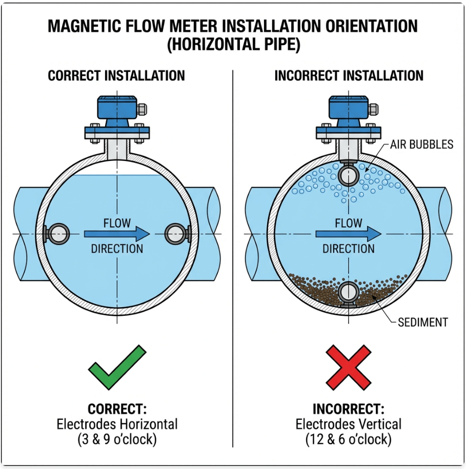
Figure 3: Proper Electrode Orientation to Avoid Air Bubbles and Sediment
Horizontal installation: Mount with electrodes at the 3 o’clock and 9 o’clock positions. Never at 12 and 6 o’clock.
Vertical installation: Flow direction must be UPWARD to ensure pipe remains full.
📘 Details: Can Magnetic Flow Meters Be Installed Vertically?
2. Straight Pipe Run Requirements
| Upstream Disturbance | Recommended Upstream | Downstream |
|---|---|---|
| Single 90° elbow | 5D | 2D |
| Two elbows (same plane) | 5D | 2D |
| Two elbows (different planes) | 10D | 2D |
| Partially open valve | 10D | 2D |
| Pump outlet | 10D | 5D |
| Reducer/Expander | 5D | 2D |
D = Pipe internal diameter
3. Grounding (Critical)
| Pipe Material | Grounding Method |
|---|---|
| Metal pipe (unlined) | Ground through pipe flanges |
| Metal pipe (lined) or Plastic pipe | Grounding rings are MANDATORY on both flanges |
Grounding ring material: Must match or exceed electrode material corrosion resistance.
Target grounding resistance: ≤ 10 Ω to earth ground.
📘 Why It Matters: Why Does A Magnetic Flow Meter Need Grounding?
4. Full Pipe Condition
The pipe must be completely filled with liquid during operation to ensure accurate measurement.
Application Suitability Check
✅ Suitable Applications
Water, wastewater, sewage, sludge
Acids, bases, and corrosive chemicals
Mining slurries and tailings
Food & beverage (juice, milk, beer, syrup)
Pharmaceutical solutions
Drilling mud and cement slurry (high-pressure type)
Remote water systems (battery-operated type)
❌ Not Suitable
Hydrocarbons (oil, diesel, gasoline)
Deionized/distilled water (conductivity < 5 μS/cm)
Gases and steam
Common Industries & Applications
Water & Wastewater Treatment
Raw water intake and distribution monitoring
Sewage and sludge flow measurement
Chemical dosing control (coagulants, polymers)
📘 Application Focus: What Is An Electromagnetic Flow Meter For Wastewater?
Oil & Gas / Geological Exploration
Drilling mud measurement (high-pressure type, up to 42 MPa)
Cement slurry monitoring
High-pressure water injection systems
Food & Beverage
Ingredient batching and recipe control
CIP (Clean-in-Place) monitoring
Sanitary tri-clamp connections with PFA liners
Mining & Minerals Processing
Tailings and slurry flow monitoring
Thickener underflow control
Tungsten carbide coated electrodes for extreme abrasion resistance
Municipal Water Distribution
Large diameter trunk main monitoring (insertion type)
Remote well monitoring (battery-operated with GSM)
Revenue metering and leak detection
Troubleshooting Checklist
| Symptom | Probable Cause | Corrective Action |
|---|---|---|
| Reading = 0 | Empty pipe, low flow, or cut-off active | Verify pipe is full; check low-flow cut-off setting |
| Fluctuating reading | Air bubbles or poor grounding | Check orientation; install grounding rings |
| Reading too high | Insulating coating on electrodes | Clean electrodes; maintain velocity > 0.5 m/s |
| Reading too low | Conductive coating or bypass leak | Clean electrodes; check for valve leakage |
| No output | Wiring fault or conductivity too low | Check wiring; verify fluid conductivity ≥ 5 μS/cm |
📘 Full Guide: Magnetic Flow Meter Troubleshooting: Simple Fixes for Common Problems
Conclusion
The magnetic flow meter combines electromagnetic physics with rugged industrial construction to deliver reliable, maintenance-free flow measurement. Soaring Instrument offers a complete product range to meet virtually any application:
| Type | Diameter | Key Feature |
|---|---|---|
| Pipeline (Inline) | DN3 – DN3000 | Standard industrial applications |
| Insertion | DN100 – DN3000 | Hot-tap installation, no shutdown required |
| High-Pressure | DN25 – DN250 | Up to 42 MPa for drilling and injection |
| Battery-Operated | Various | 5-10 year battery life, GSM remote transmission |
Key specifications:
Accuracy: ±0.5% (±0.2% available)
Velocity Range: 0.1 – 15 m/s
Turndown Ratio: 150:1
Protection: IP65/IP68, Explosion-proof ExdII CT6
Three keys to successful implementation:
Verify conductivity: ≥ 5 μS/cm (≥ 20 μS/cm for high-pressure type)
Select materials: Match liner and electrode to fluid chemistry and temperature
Install correctly: Full pipe, proper orientation, adequate straight run, proper grounding
Need Engineering Assistance?
Soaring Instrument engineers are available to review your application requirements and recommend the optimal configuration—including diameter, materials, and output options.
Contact Our Engineering Team | View Full Product Specifications