Getting accurate measurements from a clamp on ultrasonic flow meter depends heavily on proper installation. Even the most expensive meter will fail if the transducers aren’t mounted correctly.
In this guide, we’ll cover the essential steps to ensure a strong signal and reliable data.
1. Verify Upstream and Downstream Requirements
Like all flow meters, clamp on ultrasonic meters require adequate straight pipe runs to ensure a developed flow profile. Turbulence from elbows, valves, or pumps will cause unstable readings.
| Configuration | Upstream Requirement | Downstream Requirement |
|---|---|---|
| Standard installation | 10D | 5D |
| After elbow | 15D | 5D |
| After valve | 20D | 5D |
| After pump | 30D | 5D |
D = pipe diameter
Rule of Thumb: If you can’t meet these requirements, try to place the meter where the upstream straight run is at least twice as long as the downstream run (2:1 ratio).
2. Choose the Right Installation Method: V-Method vs Z-Method
Choosing the right transducer mounting method is critical for signal quality:
V-Method (Reflect Mode)
Transducers are mounted on the same side of the pipe. The ultrasonic sound bounces off the opposite pipe wall and reflects back to the second transducer.
Best for: Small to medium pipes (DN15 – DN400)
Advantage: Double path length increases measurement accuracy.
Diagram:
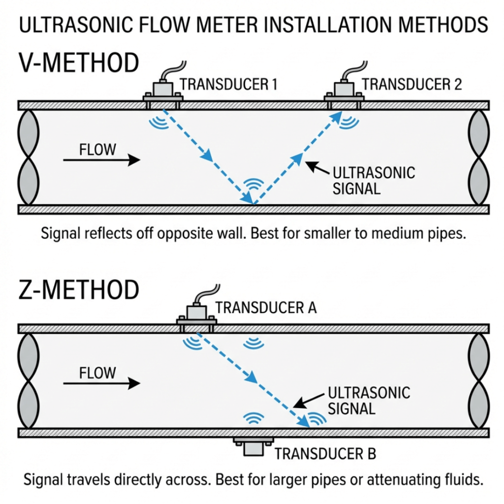
Z-Method (Direct Mode)
Transducers are mounted on opposite sides of the pipe. The sound travels directly across the pipe.
Best for: Large pipes (>DN400) or difficult applications (old, scaled, or lined pipes).
Advantage: Stronger signal penetration, as the sound only crosses the fluid once.
3. Surface Preparation (Critical Step)
Signal quality depends on good acoustic coupling. If the pipe surface is rough, the signal will scatter.
Clean the pipe surface thoroughly. Remove all loose rust, paint, and scale using a wire brush or sander until you see bare metal.
Check for internal corrosion using a wall thickness gauge if available.
Avoid longitudinal welds. Never mount transducers directly over a pipe seam, as the weld can distort the signal.
4. Apply Coupling and Mount Transducers
Apply coupling gel generously to the face of the transducers. This eliminates air gaps between the sensor and the pipe.
Position transducers at the exact spacing calculated by the flow meter transmitter.
Secure mounting using stainless steel straps or magnetic brackets. Ensure they are tight enough to prevent movement but not so tight that they deform the sensor.
5. The "Lining Killer" Warning
If your pipe has an internal lining (cement, rubber, epoxy), there must be a perfect bond between the lining and the pipe wall.
Risk: Even a microscopic air gap between the liner and the pipe will block the ultrasonic signal completely.
Solution: If you suspect a debonded liner, try the Z-Method or move the measurement point to a different section of pipe.
Conclusion
Proper installation is the difference between a meter that works for 20 years and one that never gives a stable reading. Take the time to prepare the surface and align the sensors correctly.