Over 60% of vortex meter issues stem from incorrect installation rather than device failure. Early problem detection can prevent costly process interruptions and measurement errors.
Vortex flowmeter troubleshooting involves checking power supply (18-32V DC), verifying signal output (pulse/frequency), inspecting for pipe vibrations/deposits, and confirming proper grounding. Common issues include no flow signal (50% cases), unstable readings (30%), and zero drift (20%), each requiring specific diagnostic steps.
Vortex Meter Diagnosis
Effective troubleshooting requires understanding both electrical and mechanical aspects. The following sections break down problem-solving approaches for various flow measurement scenarios.
How Do You Troubleshoot a Vortex Flow Meter?
Four-step diagnostic procedure:
Vortex Meter Troubleshooting Matrix
| Symptom | Primary Checks | Secondary Checks | Solution |
|---|---|---|---|
| No signal | Power supply | Wiring connections | Replace cable/sensor |
| Fluctuating values | Flow conditions | Meter orientation | Install dampener |
| Zero drift | Process temperature | Sensor fouling | Clean/recalibrate |
| Low amplitude | Fluid viscosity | Piezo condition | Replace detector |
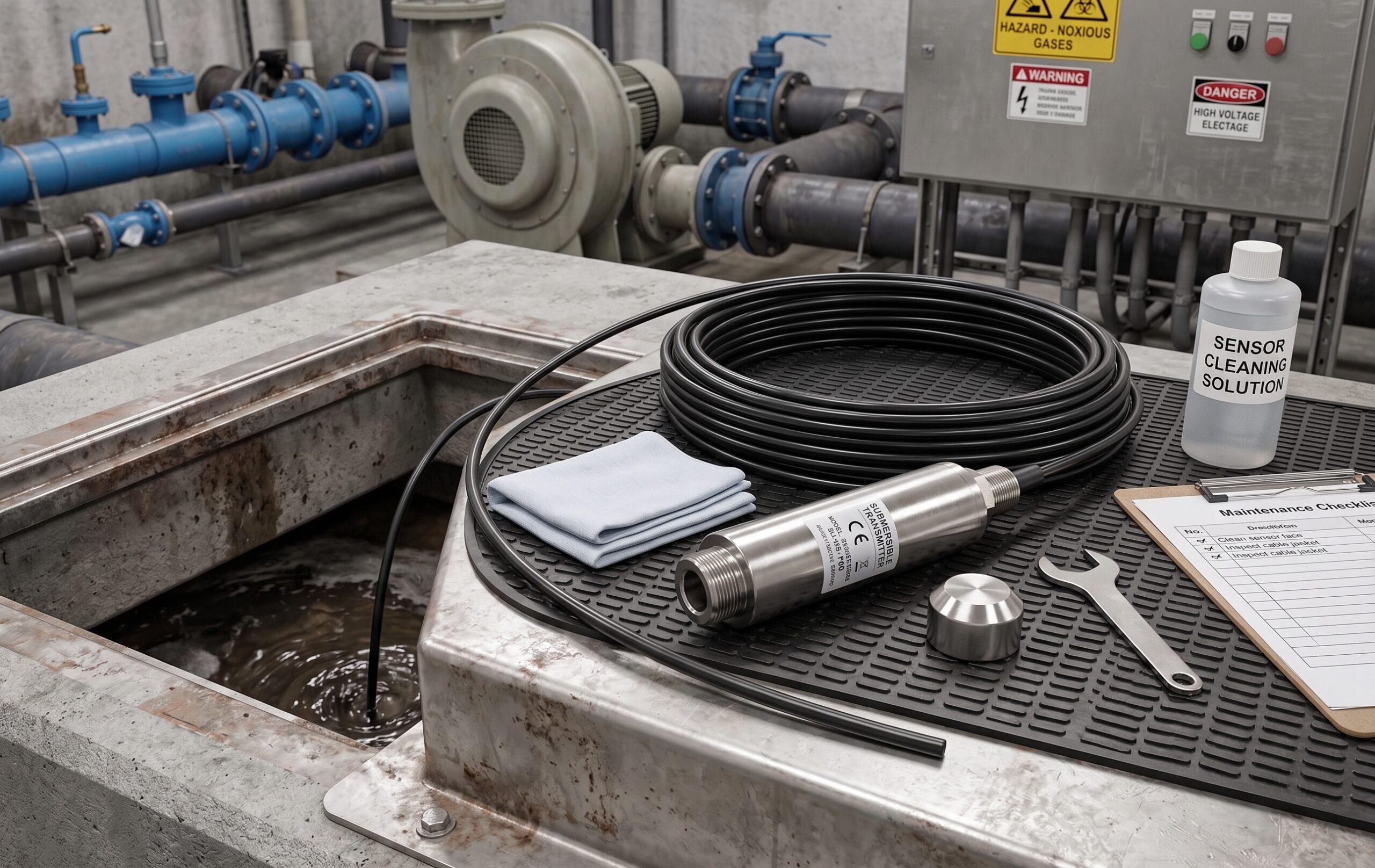
Diagnostic Tools Checklist
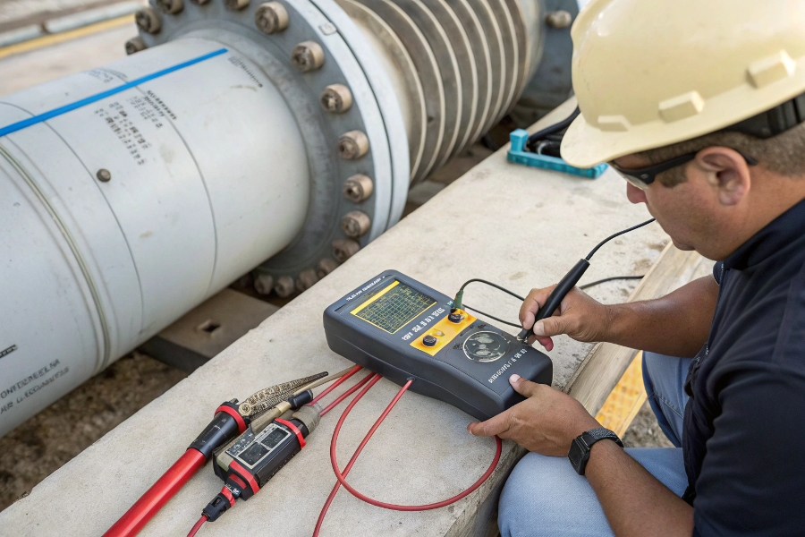
Electrical Testing
- Multimeter (voltage/current)
- Oscilloscope (signal shape)
- HART communicator
- Insulation tester
Mechanical Inspection
- Ultrasonic thickness gauge
- Borescope for deposits
- Vibration analyzer
- Pressure gauge
Process Verification
- Flow rate comparison
- Density/temp checks
- Bubble/debris inspection
- Pipe strain examination
%(percentage)troubleshooting tools
Signal Analysis Guide
Normal Signal:
- Clean sine wave
- Consistent amplitude
- Frequency matches flow
Problem Patterns:
- Flatline = No power/dead sensor
- Erratic spikes = Vibration
- Declining wave = Fouling
- Intermittent = Wiring issues
How Do You Troubleshoot a Flow Meter?
Three universal troubleshooting approaches:
Flow Meter Diagnostic Protocol
| Technique | Application | Equipment Needed | Time Required |
|---|---|---|---|
| Process isolation | All types | Valves/gauges | 1-2 hours |
| Signal tracing | Electronic | Multimeter | 30 mins |
| Component swap | Field devices | Spare parts | 4-8 hours |
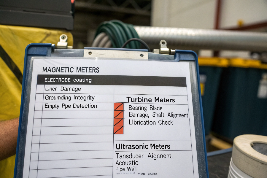
Technology-Specific Checks
Magnetic Meters
- Electrode coating
- Liner damage
- Grounding integrity
- Empty pipe detection
Turbine Meters
- Bearing rotation
- Blade damage
- Shaft alignment
- Lubrication check
Ultrasonic Meters
- Transducer alignment
- Acoustic coupling
- Pipe wall condition
- Transmit time ratio
%(percentage)flow meter diagnosis
Multi-Meter Debugging
Measurement Error Sources
- Common Across All Types:
- Improper calibration
- Incorrect K-factor
- Fluid property changes
- Installation effects
- Pipe diameter mismatch
What Is the Pressure Drop Across a Vortex Flowmeter?
Pressure impact analysis:
Vortex ΔP Performance Data
| Condition | Standard ΔP | Maximum Allowable | Recovery Factor |
|---|---|---|---|
| Clean pipe | 0.2 bar | 0.35 bar | 85% |
| Partial fouling | +15% | 0.4 bar | 75% |
| High viscosity | +25% | 0.45 bar | 65% |
| Overspeed | +50% | 0.6 bar | 50% |
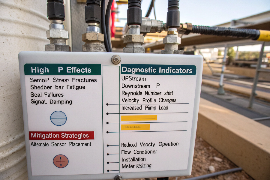
Pressure-Related Faults
High ΔP Effects
- Sensor stress fractures
- Shedder bar fatigue
- Seal failures
- Signal damping
Diagnostic Indicators
- Upstream/downstream ΔP
- Reynolds number shift
- Velocity profile changes
- Increased pump load
Mitigation Strategies
- Alternate sensor placement
- Reduced velocity operation
- Flow conditioner install
- Meter resizing
%(percentage)pressure impact
ΔP Effects
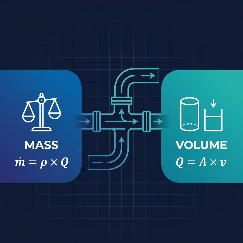
ΔP Calculation Method
- Formula: ΔP = K × ρ × v²
Where:
K = Meter coefficient (0.5-1.5)
ρ = Fluid density (kg/m³)
v = Velocity (m/s) - Example (water @ 2m/s):
1 × 1000 × 4 = 4000 Pa (0.04 bar)
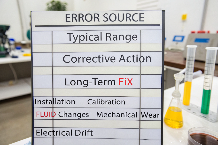
What Are the Sources of Error in a Flow Meter?
Five primary error categories:
Flow Measurement Error Analysis
| Error Source | Typical Range | Corrective Action | Long-Term Fix |
|---|---|---|---|
| Installation | ±5-15% | Flow conditioning | Repipe section |
| Calibration | ±0.5-3% | Field adjustment | Lab recalibration |
| Fluid changes | ±2-10% | Parameter update | Density compensation |
| Mechanical wear | ±1-5%/year | Component replace | Upgrade materials |
| Electrical drift | ±0.1-1% | Circuit check | Board replacement |
Quantifying Errors
Installation Effects
- Elbows: +3-8% error
- Valves: +5-12% error
- Expansions: +2-6% error
- Vibrations: ±10% fluctuation
Fluid Property Impacts
- Density 1% change = 0.5% error
- Viscosity 10% change = 1-3% error
- Temperature 10°C = 0.1-2% error
- Solids content = 2-15% error
%(percentage)error sources
Measurement Uncertainty
Reducing Measurement Errors
Proven Methods:
- Factory flow calibration
- Annual verification checks
- Proper straight pipe runs
- Advanced signal processing
Error Source Vortex Impact Magnetic Impact Turbine Impact Pulsation High None Medium Bubbles Medium High Low Coatings Low Critical High Vibration Critical Low Medium
Conclusion
Vortex flowmeter troubleshooting requires systematic checks of electrical signals, mechanical conditions, and process parameters. Pressure drop analysis serves as both diagnostic tool and performance indicator, while understanding error sources enables targeted corrections. Effective maintenance combines regular signal verification (monthly), mechanical inspection (quarterly), and full calibration (annually) to maintain ±1% accuracy in most industrial applications.