Factory teams often face challenges when installing vortex meters, leading to inaccurate measurements and unnecessary downtime. Proper installation makes all the difference.
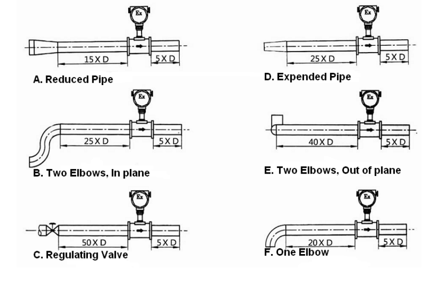
Vortex flow meters require 15 pipe diameters (15D) upstream and 5D downstream straight piping, proper orientation based on fluid type, adequate supports to minimize vibration, and environmental protection from extreme conditions. The minimum distance ensures fully developed flow profile for accurate measurement.
Proper Installation Example
Understanding installation standards prevents 90% of vortex meter performance issues before they occur.
What Are the Requirements for a Vortex Flow Meter?
Five critical installation prerequisites:
Installation Checklist Table
| Requirement | Specification | Reason |
|---|---|---|
| Pipe Straightness | 15D upstream, 5D downstream | Flow profile development |
| Orientation | Horizontal for gases, vertical upwards for liquids | Air bubble/particle elimination |
| Support | Rigid mounting ±1mm alignment | Vibration reduction |
| Environment | -20°C to 60°C ambient | Electronics protection |
| Access | Sufficient service space | Maintenance clearance |
Fluid-Specific Considerations
-
Steam Applications
- Install condensate pots
- Use thermal expansion joints
- Include pipe anchors
-
Gas Services
- Position downstream of regulators
- Avoid pulsation sources
- Consider density compensation
-
Liquid Processes
- Keep always full in vertical pipes
- Eliminate air pockets
- Install sediment filters
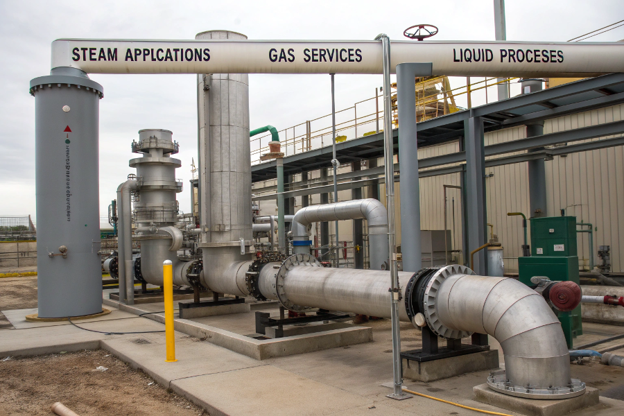
Fluid-Specific Requirements
Common Mistakes to Avoid
- Ignoring manufacturer’s minimum straight-run
- Mounting near pumps/compressors
- Using flexible hose connections
- Installing in pulsating flow conditions
- Omitting grounding provisions
How to Calibrate a Vortex Meter?
Three calibration approaches with step-by-step guidance:
Calibration Method Comparison
| Method | Accuracy | Equipment Needed | Frequency |
|---|---|---|---|
| Factory Cal | ±0.5% | Flow lab reference | Every 5 years |
| Field Verify | ±1-2% | Clamp-on ultrasonic | Annual |
| K-Factor Adjust | ±2-5% | Process knowledge | When deviations noticed |
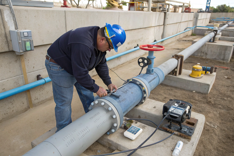
Field Verification Process
-
Preparation
- Confirm stable process conditions
- Gather P&IDs and meter specs
- Prepare verification equipment
-
Measurement
- Take 10 flow rate samples
- Record temperature/pressure
- Note any pulsations
-
Analysis
- Compare with meter reading
- Calculate % deviation
- Check against historical data
-
Adjustment
- Enter new K-factor if needed
- Document calibration changes
- Set next verification date
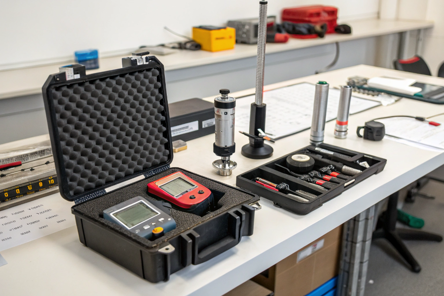
Field Verification In Progress
K-Factor Determination
- Original factory K-factor = 10,000 pulses/m³
- Field measurement shows 2% low reading
- New K-factor = 10,000 × 1.02 = 10,200
- Enter in meter electronics
- Verify again after 24 hours
How Should a Flow Meter Be Installed?
Five installation scenarios with best practices:
Orientation Guidelines
| Fluid Type | Recommended Orientation | Notes |
|---|---|---|
| Clean Liquids | Vertical upward flow | Prevents air accumulation |
| Steam | Horizontal with elevation | Ensures condensate drainage |
| Gases | Horizontal or vertical up | Avoids liquid collection |
| Slurries | Vertical upward | Prevents settling |
| Cryogenic | Downward inclined | Prevents vapor locks |
Mechanical Installation Steps
-
Pipe Preparation
- Cut pipe square
- Remove burrs
- Clean interior
-
Gasket Installation
- Use proper gasket material
- Align carefully
- Avoid over-tightening
-
Meter Mounting
- Observe flow direction arrow
- Use proper supports
- Check alignment
-
Electrical Connections
- Follow NEMA ratings
- Properly ground
- Seal conduits
-
Startup Checks
- Zero verification
- Leak test
- Initial readings
Step-by-Step Installation
Special Condition Installations
- High Vibration Areas: Use flexible couplings + additional supports
- Outdoor Locations: Install weatherproof enclosures
- Hazardous Areas: Comply with EX certification requirements
- High Temperature: Allow for thermal expansion
- Underground: Provide waterproof junction boxes
What Is the Minimum Distance for a Flow Meter?
Four critical distance requirements:
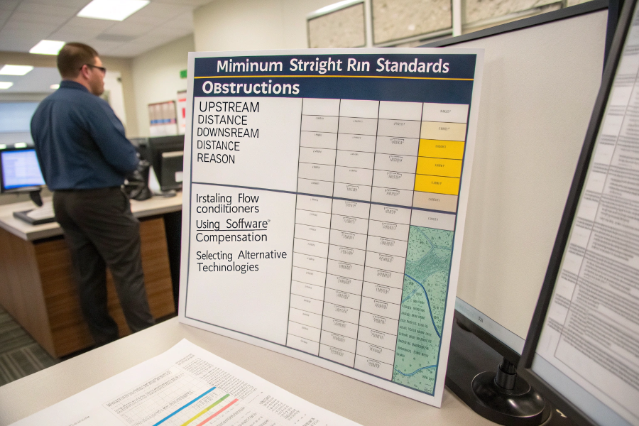
Minimum Straight-Run Standards
| Obstruction | Upstream Distance | Downstream Distance | Reason |
|---|---|---|---|
| Single 90° Elbow | 20D | 5D | Flow disturbance |
| Reducer | 10D | 5D | Velocity profile |
| Pump | 50D | 10D | Pulsation effect |
| Valve | 30D (fully open) | 10D | Turbulence |
| T-Junction | 40D | 10D | Swirl removal |
When Distances Can’t Be Met
-
Install Flow Conditioner
- Perforated plate type
- Tube bundle design
- Increases cost but saves space
-
Use Software Compensation
- Advanced algorithms
- Requires characterization
- Limited effectiveness
-
Select Alternative Technology
- Ultrasonic meters
- Coriolis meters
- Depends on application
%(percentage)straight-run requirements
Pipe Configuration Impact
Industry-Specific Exceptions
- ASME B31.1 Power Piping: Allows 10D upstream with conditioner
- API Petroleum Standards: Requires 30D for custody transfer
- FDA Sanitary Standards: Demands special geometric conditioners
- ISO Measurement Standards: Recommends 15D as absolute minimum
Conclusion
Proper vortex flow meter installation requires strict adherence to 15D upstream and 5D downstream piping requirements, correct orientation based on fluid properties, adequate support to minimize vibration, and appropriate environmental protection. Calibration should follow manufacturer guidelines with regular field verification, while special conditions demand customized solutions. When minimum straight-pipe runs can’t be achieved, flow conditioners or alternative technologies become necessary. Following