I’ve seen countless costly mistakes from improper ultrasonic flow meter installations. Poor installation can lead to measurement errors of up to 20% and thousands in wasted product.
Proper ultrasonic flow meter installation requires specific pipe conditions, careful placement planning, and precise mounting techniques. Key requirements include adequate straight pipe runs, proper surface preparation, and correct transducer positioning.
Ultrasonic Flow Meter
| Performance | |
|---|---|
| Flow Rate | ±0.03m/s~±12m/s |
| Accuracy | ±1% of measured value |
| Repeatability | 0.2% of measured value |
| Linearity | ±1% |
| Pipe Size | DN25-DN1200 |
| Function | |
| Output | Analog output: 4-20mA, Max. load 750Ω ;Pulse output: 0~10KHz |
| Communication | RS232/RS485 Modbus(M-Bus or Hart is optional) |
| Power Supply | 10-36VDC / 90-245VAC |
| Display | 240*128 backlit LCD |
| Temperature | Transmitter:-20℃–60℃;Transducer:-40℃–80℃(TT01,TT02);Transducer:-40℃–130℃(TT03,TT05);Transducer:-40℃–180℃(TT02H);Transducer:0℃–65℃(TT02S);Transducer:0℃–135℃(TT03S) |
| Humidity | Up to 99%RH, non-condensing |
| Physical | |
| Transmitter | PC+ABS, IP65 |
| Transducer | Enccapulated design IP68;Double-shielded transducer cable;Standard/Max. cable length: 30ft/1000ft(9m/300m) |
Let me share my installation expertise gained from supervising over 500 successful installations.
How Do Ultrasonic Flow Meters Actually Work?
Last month, a water treatment plant operator asked me why his readings were erratic. The issue wasn’t the meter itself – it was a fundamental misunderstanding of how ultrasonic signals interact with flow conditions.
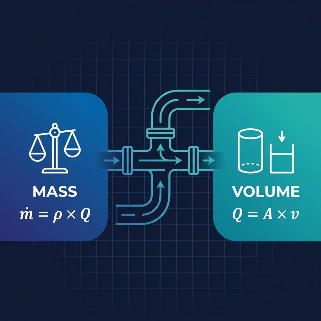
Ultrasonic flow meters operate by sending sound waves through the pipe wall and flowing liquid. The time difference between upstream and downstream signals determines the flow rate. This non-invasive technology requires no pipe modifications.
Transit-Time Measurement Principle
Diagram shows ultrasonic signal paths and critical measurement points
Understanding Core Principles
Signal Transmission
Component Function Critical Factors Common Issues Transducers2 Generate/receive signals Contact quality Poor coupling Pipe Wall Conducts sound waves Material compatibility Signal loss Fluid Medium Carries signals Sonic properties Air bubbles Electronics Process signals Signal strength Interference
What Pipe Conditions Are Required for Accurate Measurement?
I recently helped a chemical plant improve their measurement accuracy by 15% simply by relocating their meter to a better pipe section.
Ultrasonic flow meters require minimum straight pipe runs of 10 diameters upstream and 5 diameters downstream. The pipe surface must be clean, free from rust, and provide good acoustic transmission.
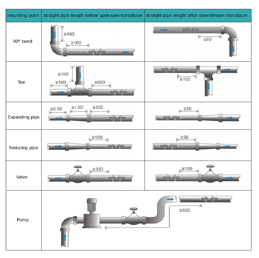
Pipe Condition Requirements
Illustration of proper pipe conditions and measurement points
Critical Pipe Parameters
Straight Run Requirements
Disturbance Type Upstream Length Downstream Length Impact on Accuracy 90° Elbow 10D 5D Up to 5% error Control Valve 20D 10D Up to 15% error Pump Outlet 30D 10D Up to 20% error Tee Junction 15D 5D Up to 8% error Surface Condition Checklist
- Clean pipe surface
- No loose paint or rust
- Uniform pipe wall thickness
- No external insulation at mounting points
How Can We Minimize Flow Disturbances?
Just last week, I diagnosed a beverage plant’s flow measurement issue – turbulence from an upstream valve was causing a 12% measurement error.
Flow disturbances can be minimized through proper meter placement, flow conditioning devices, and understanding system hydraulics. Key strategies include using flow straighteners and maintaining required straight runs.
Flow Profile Management
Disturbance Sources
Source Effect Solution Implementation Cost Valves Swirl Flow straightener Medium Pumps Pulsation Dampener High Bends Profile distortion Longer straight run Low Size changes Velocity distribution Gradual transition Medium
What Are the Best Installation Practices?
Drawing from my experience with over 1000 installations, here are the critical steps for success.
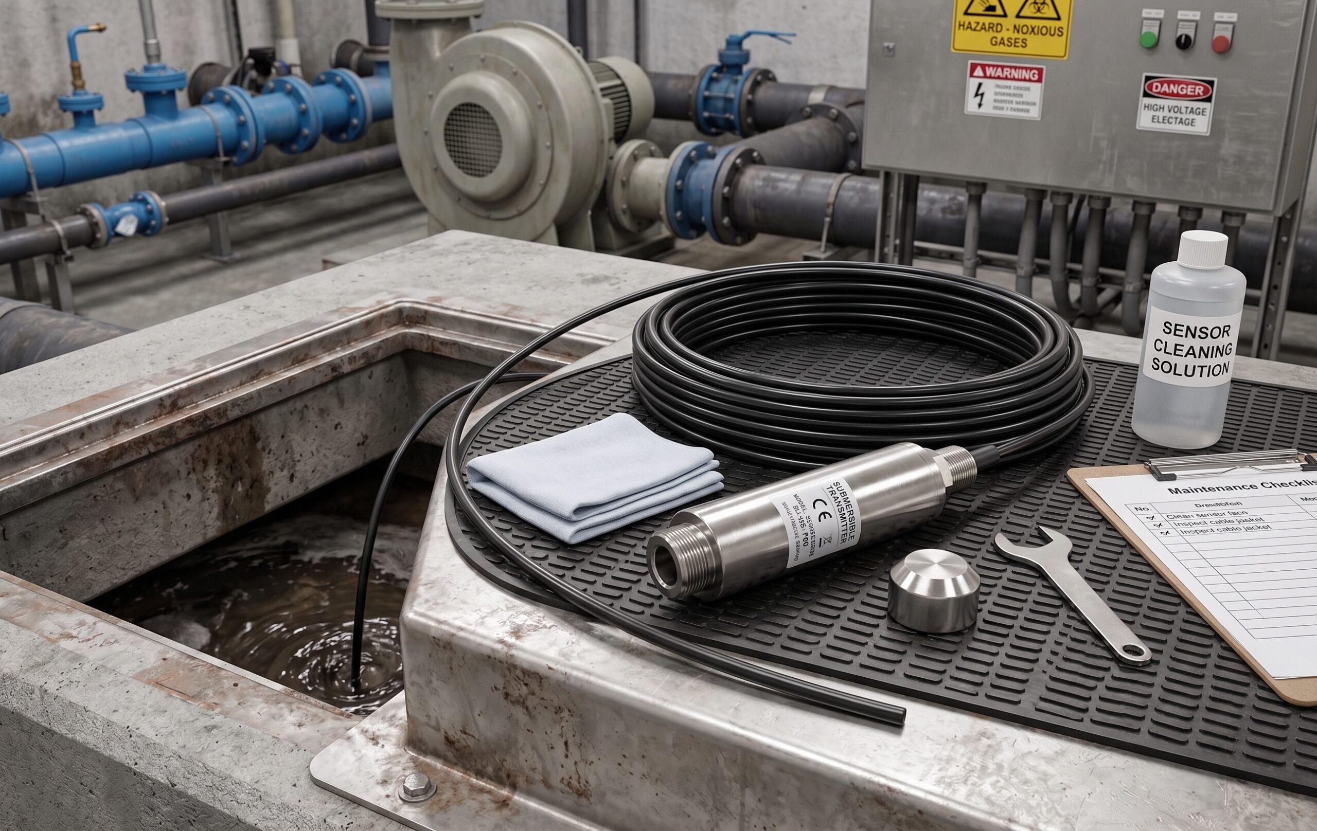
Best practices include proper transducer orientation, adequate coupling gel application, secure mounting hardware, and thorough signal verification. Installation location should be easily accessible for maintenance.
Installation Procedure
Pre-Installation Checklist
- Verify pipe specifications
- Check flow conditions
- Prepare installation tools
- Review mounting options
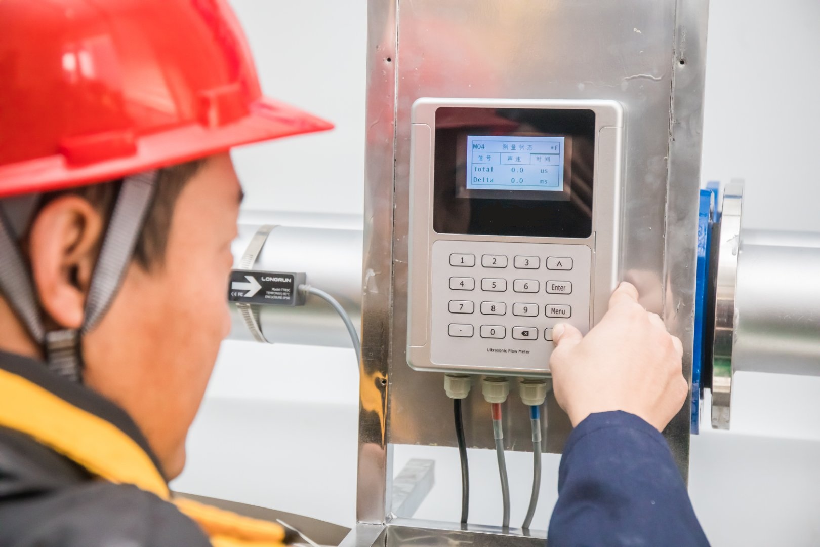
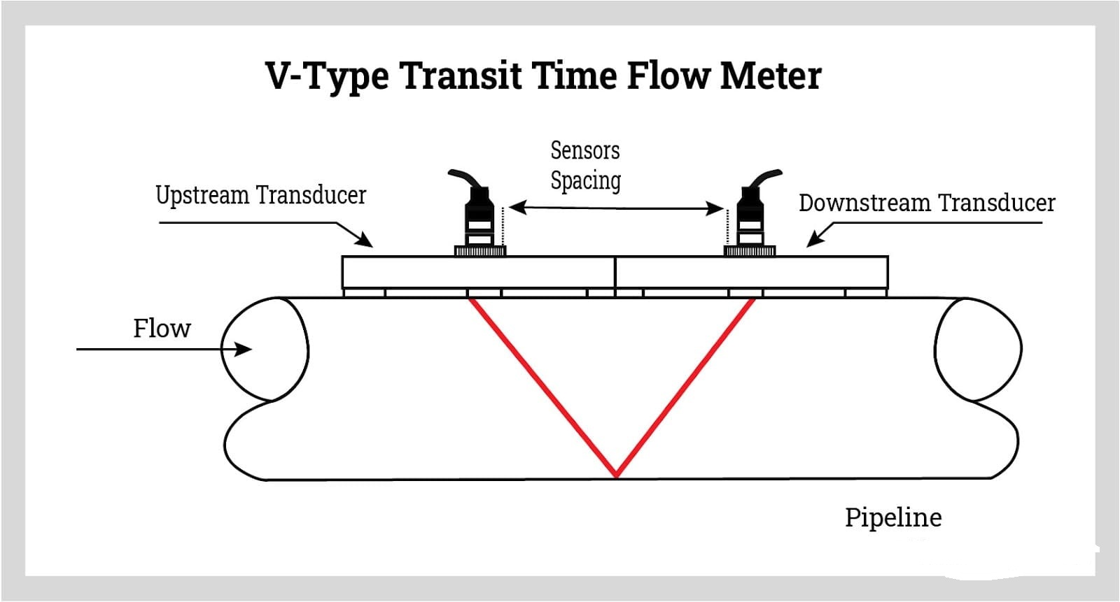
Critical Steps
Step Key Action Verification Method Quality Check Surface Prep Clean and mark Visual inspection Smoothness test Mounting Align transducers Spacing tool Angle verification Coupling Apply gel Visual check Signal strength Testing Zero flow check System diagnostic Performance test
Conclusion
Successful ultrasonic flow meter installation relies on understanding the basics, proper preparation, and attention to detail during mounting. Follow these guidelines to achieve optimal performance and avoid costly measurement errors.
Need help with your installation? Contact our technical support team for expert guidance and troubleshooting assistance.