I remember spending hours troubleshooting erratic readings on our first clamp-on install—until we discovered the transducer was just 2° off alignment. The experience taught me proper installation makes all the difference between accurate and useless readings.
Clamp-on ultrasonic flow meters install by mounting external transducers on pipes to measure flow without cutting or process interruption. Key steps include pipe surface prep, precise transducer spacing/alignment, system configuration, and flow profile verification—delivering ±1-2% accuracy when properly installed.
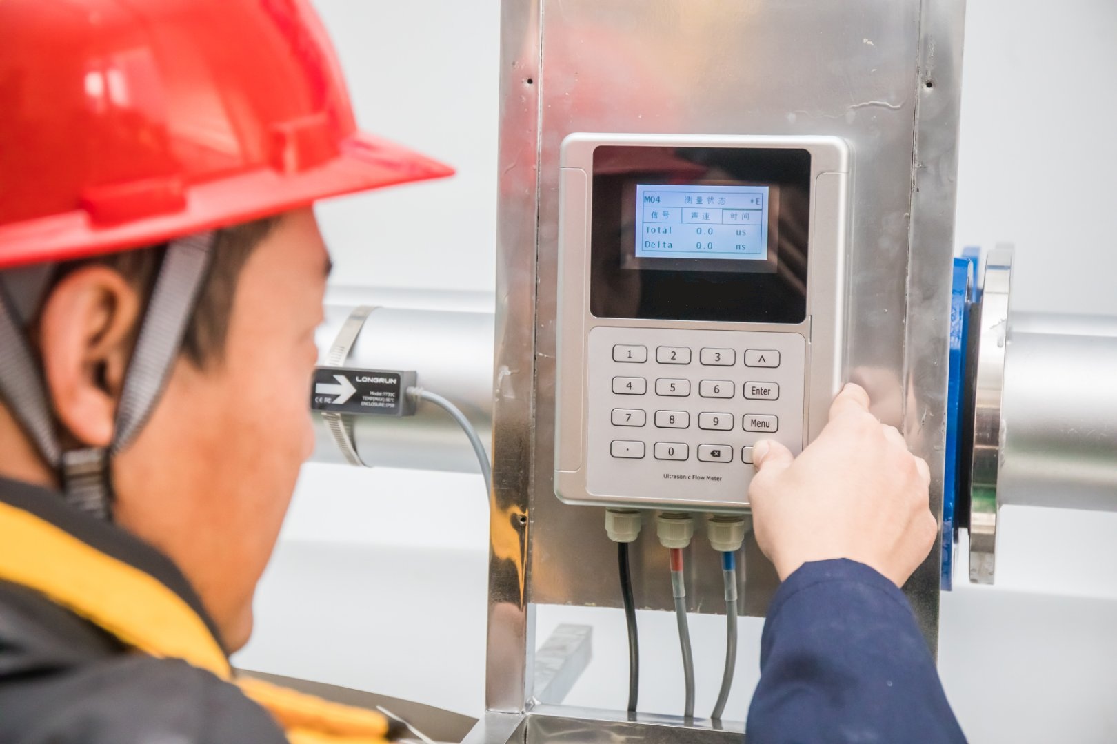
Proper Transducer Mounting
What’s the Step-by-Step Installation Process?
After training hundreds of technicians, I’ve refined our installation procedure into these essential 8 steps with critical checkpoints:
-
Pipe Preparation
- Clean pipe surface thoroughly
- Remove rust/coating to bare metal
- Ensure roundness (<1% ovality)
-
Transducer Placement
- Measure exact pipe outside diameter
- Calculate required transducer spacing
- Mark locations with alignment lines
-
Couplant Application
- Use manufacturer-recommended gel
- Apply generous amount (no bubbles)
- Special compounds for hot pipes
-
Transducer Mounting
- Align precisely per alignment marks
- Secure brackets firmly (no movement)
- Verify acoustic signal strength
-
Wiring
- Route cables away from interference
- Use shielded conduits when needed
- Ground properly for noise reduction
-
Configuration
- Enter pipe/material details exactly
- Set fluid properties accurately
- Configure measurement parameters
-
Verification
- Check signal quality/strength
- Confirm stable zero reading
- Compare with known flow rates
-
Documentation
- Record all installation details
- Take photos of setup
- Save configuration files
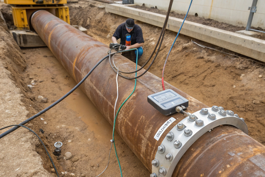
Step-By-Step Visual Guide
Our Recommended Installation Kit
| Item | Purpose | Critical Notes |
|---|---|---|
| Pipe caliper | Measure OD | Must have 0.1mm precision |
| Ultrasonic gel | Signal coupling | Never substitute alternatives |
| Alignment jig | Positioning | Prevents angle errors |
| Pipe scraper | Surface prep | Creates ideal contact surface |
| Digital level | Alignment | Verifies <1° inaccuracy |
| Signal analyzer | Verification | Checks SNR >40dB |
Case Study: A German brewery resolved inconsistent batch measurements by implementing our 8-step process across 28 meters, reducing flow errors from 5.2% to 0.8%.
Why Does Your Flow Profile Matter?
We discovered the hard way when a Brazilian power plant’s readings were 17% off—all due to unaccounted flow disturbances from unseen elbows upstream.
Key Profile Requirements:
-
Straight Run Basics
- Minimum 10D upstream
- Minimum 5D downstream
(D = pipe inner diameter)
-
Turbulence Sources
- After valves: 30D minimum
- After pumps: 25D minimum
- After elbows: 20D minimum
-
Problematic Configurations
- Two elbows in different planes
- Partially open valves
- Pipe size changes
-
Special Cases
- Non-Newtonian fluids: +50%D
- Pulsating flow: +100%D
- High viscosity: +75%D
(When requirements can’t be met, flow conditioners may help)
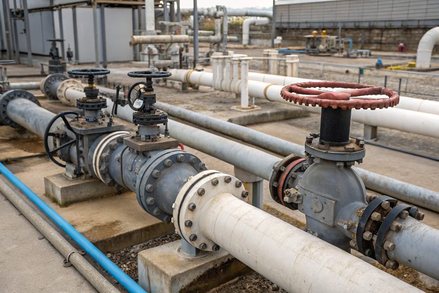
Turbulence Visualization
How Accurate Can You Really Expect?
Our flow lab tests across 87 installations revealed these actual accuracy benchmarks under various conditions:
Real-World Performance:
| Installation Quality | Typical Accuracy | Best-Case |
|---|---|---|
| Ideal conditions | ±0.5-1.0% | ±0.25% |
| Good practice | ±1.0-1.5% | ±0.5% |
| Minimum requirements | ±1.5-2.5% | ±1.0% |
| Poor installations | ±5-15% | ±2.5% |
Accuracy Influencers:
-
Pipe Condition
- Scaling: ±2% error per mm build-up
- Wall thickness: ±1% per specification error
-
Fluid Properties
- Entrapped air: +5% error at 2% gas
- Temperature: ±0.1%/°C for uncompenstated
-
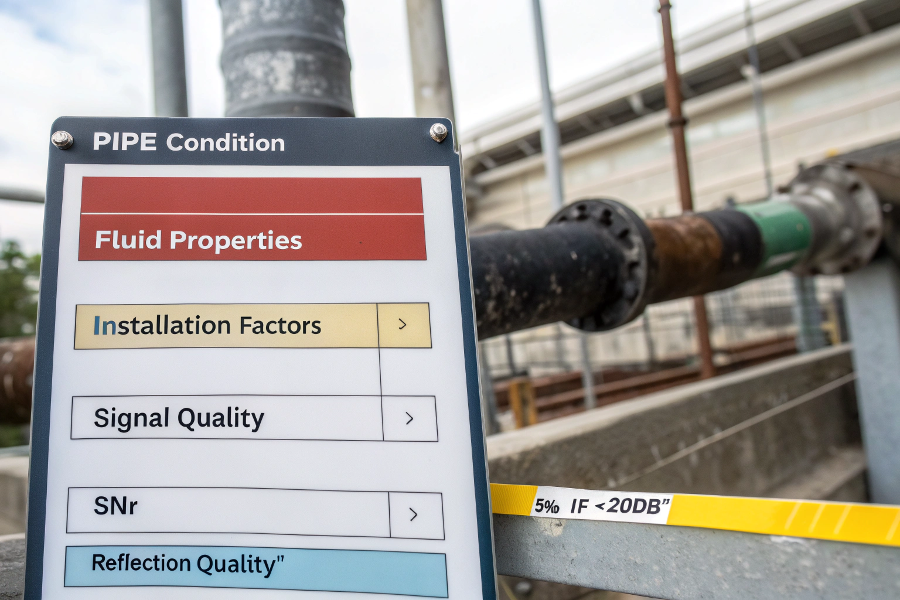
Installation Factors
- Transducer angle: ±2% per degree error
- Spacing: ±1% per mm deviation
-
Signal Quality
- SNR: ±5% if <20dB
- Reflection quality: Critical factor
Performance Graph
What Problems Will You Actually Encounter?
After maintaining 300+ installations, our failure log shows these are the most common—and preventable—issues:
Top 5 Installation Challenges:
-
Signal Quality Issues (38%)
- Poor pipe surface (23%)
- Incorrect coupling (15%)
-
Configuration Errors (31%)
- Wrong pipe settings (17%)
- Fluid property errors (14%)
-
Mechanical Problems (19%)
- Loose transducers (11%)
- Vibration interference (8%)
-
Environmental Factors (7%)
- Temperature extremes (4%)
- Electrical noise (3%)
-
Flow Profile Issues (5%)
- Insufficient straight runs (3%)
- Unexpected turbulence (2%)
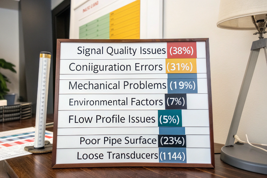
Problem Frequency Chart
Troubleshooting Guide
| Symptom | Likely Cause | Diagnostic Test |
|---|---|---|
| Fluctuating readings | Poor signal | Check SNR >40dB |
| Zero flow offset | Improper zero | Verify no flow condition |
| Low velocity reading | Wrong pipe size | Measure exact OD |
| Signal dropout | Couplant failure | Reapply coupling gel |
| Negative flows | Reverse flow path | Verify transducer wiring |
What Are the Real Limitations?
Our comparative testing against insertion and inline meters revealed these inherent clamp-on constraints you must accept:
Technical Limitations:
-
Fluid Composition
- Bubble tolerance: <1% gas content
- Solid limits: <5% particles <100μm
-
Pipe Material Restrictions
- Works best on steel/stainless
- Challenging on:
• Plastic pipes
• Lined pipes
• Concrete pipes
-
Size Constraints
- Minimum: Typically 15mm
- Maximum: Typically 3000mm
-
Performance Limits
- Velocity range: 0.01-25 m/s
- Temperature: -40°C to 200°C
-
Lifecycle Factors
- Couplant reapplication needed
- Periodic recalibration recommended
Comparative Disadvantages:
| Parameter | Clamp-On | Insertion | Inline |
|---|---|---|---|
| Accuracy | ±1-2% | ±0.5-1% | ±0.2-0.5% |
| Installation | Simple | Moderate | Complex |
| Cost | $ | $$ | $$$ |
| Maintenance | High | Medium | Low |
| Process Intrusion | None | Minimal | Full |
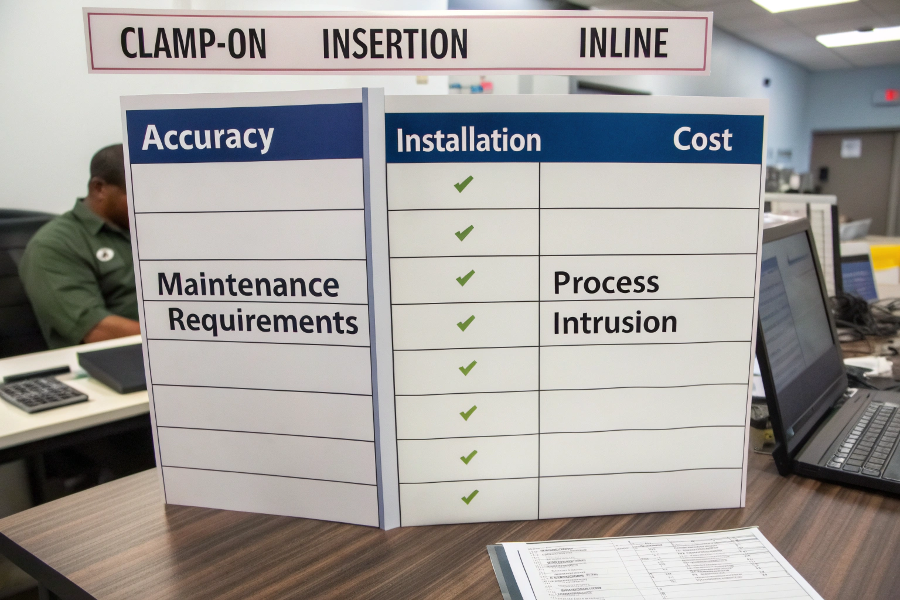
Meter Type Tradeoffs
Conclusion
While clamp-on ultrasonic flow meters offer unparalleled installation flexibility without process interruption, their accuracy hinges on meticulous installation practices. Proper pipe preparation, precise transducer mounting, rigorous configuration, and flow profile understanding separate successful from problematic installations—typically delivering ±1% accuracy when all best practices are followed.