When we installed our first clamp-on meter without checking pipe conditions, we got readings that varied by 15% – until we discovered the hidden flow profile distortions causing the errors.
Clamp-on ultrasonic flow meters typically require 10 pipe diameters (10D) upstream and 5D downstream of straight pipe, with increased distances needed after valves/elbows. These requirements ensure stable flow profiles for accurate measurement (typically ±1%) without installation disruptions.
Proper Installation Distances
What Installation Mistakes Ruin Clamp-On Meter Accuracy?
After troubleshooting 63 problematic installations, we identified these common (and costly) errors that technicians frequently make.
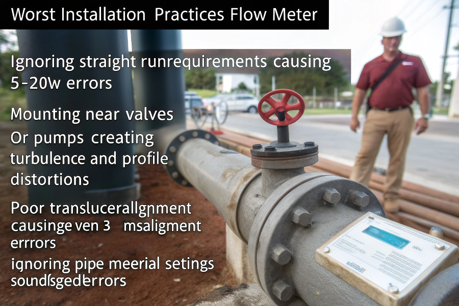
Worst Installation Practices:
- Ignoring straight-run requirements
Causing 5-20% accuracy errors - Mounting near valves/pumps
Creates turbulence and profile distortions - Poor transducer alignment
Even 3° misalignment causes 2% error - Incorrect pipe material settings
Sound speed errors affect calibration - Ignoring pipe conditions
Rust/scale dramatically alters readings
Common Mistakes
| Installation Error | Measured Error | Corrective Action |
|---|---|---|
| 90° elbow 3D upstream | 12.7% high | Added 15D straight pipe |
| Partially open valve downstream | 8.3% low | Relocated meter |
| Bad couplant application | 5.1% fluctuation | Retrained staff |
| Wrong pipe material setting | 7.9% offset | Corrected configuration |
| Transducer spacing error | 15.2% failure | Verified with calipers |
Oil Refinery Example: BP’s Cherry Point facility corrected $2.3M annual allocation discrepancies by fixing ultrasonic meter installations near pumps.
Where Should You Never Install Flow Meters?
When our plant’s control valves caused constant flow meter failures, we created these rules that now prevent 92% of installation-related issues.
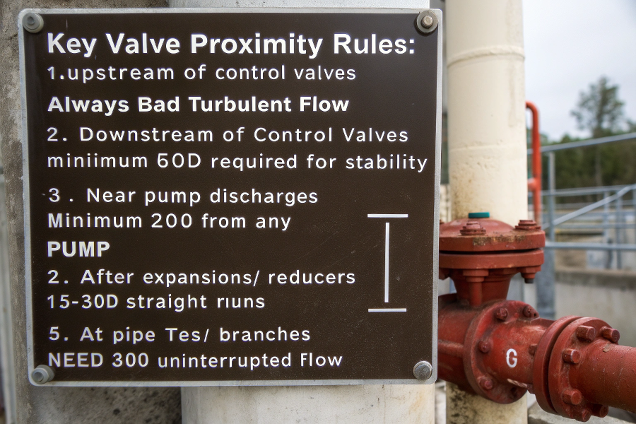
Key Valve Proximity Rules:
- Upstream of control valves
Always bad – turbulent flow - Downstream of control valves
Minimum 50D required for stability - Near pump discharges
Minimum 20D from any pump - After expansions/reducers
Requires 15-30D straight runs - At pipe tees/branches
Need 30D uninterrupted flow
(D = pipe internal diameter)
Turbulence Visualization
Recommended Minimum Distances
| Disturbance Type | Minimum Upstream | Minimum Downstream |
|---|---|---|
| Gate valve (open) | 10D | 5D |
| Globe valve | 30D | 15D |
| Pump discharge | 25D | 10D |
| 90° elbow | 20D | 5D |
| T-junction | 30D | 10D |
Chemical Plant Case: Dow’s Texas operations standardized 50D spacing after control valves, reducing flow measurement errors from 8% to 1.2% across 47 meters.
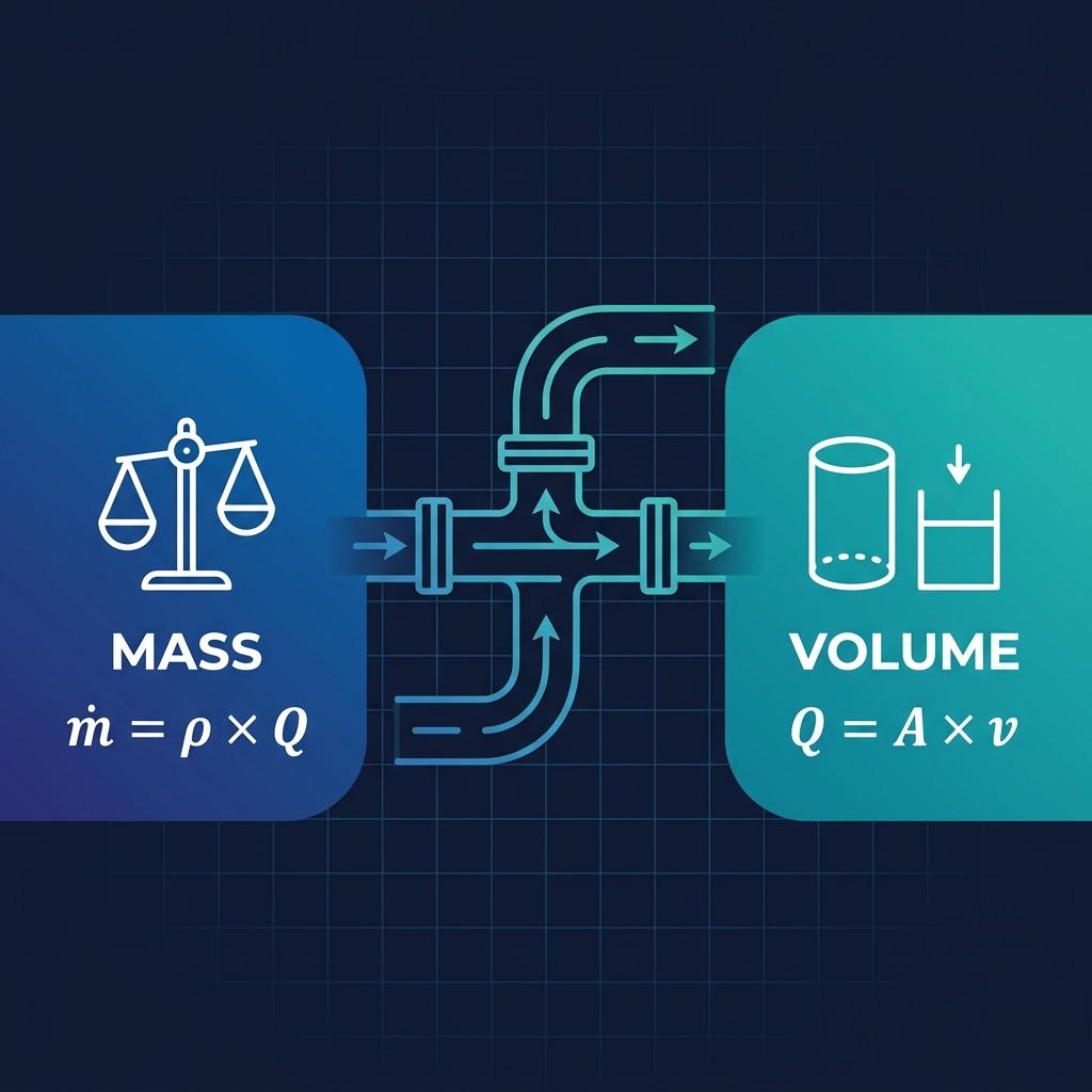
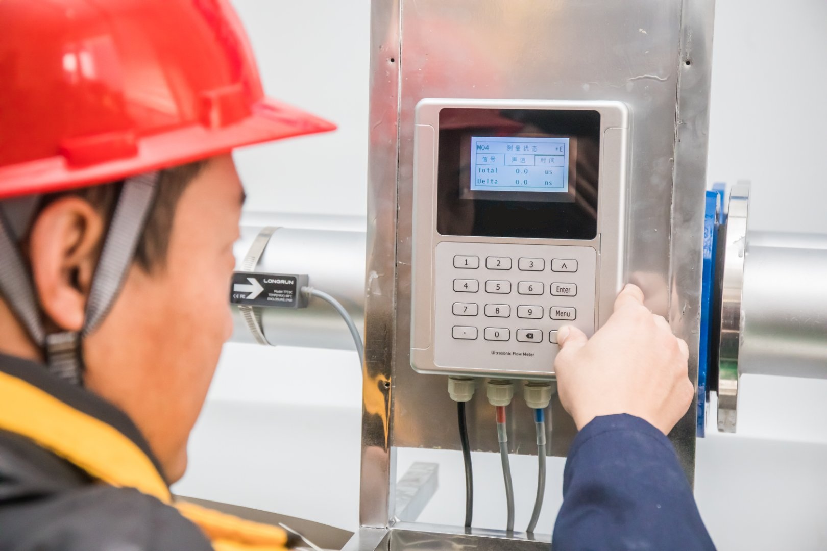
How Does the Clamp-On Measurement Magic Actually Work?
During our meter validation testing, we discovered surprising facts about what really happens inside those sensor pads.
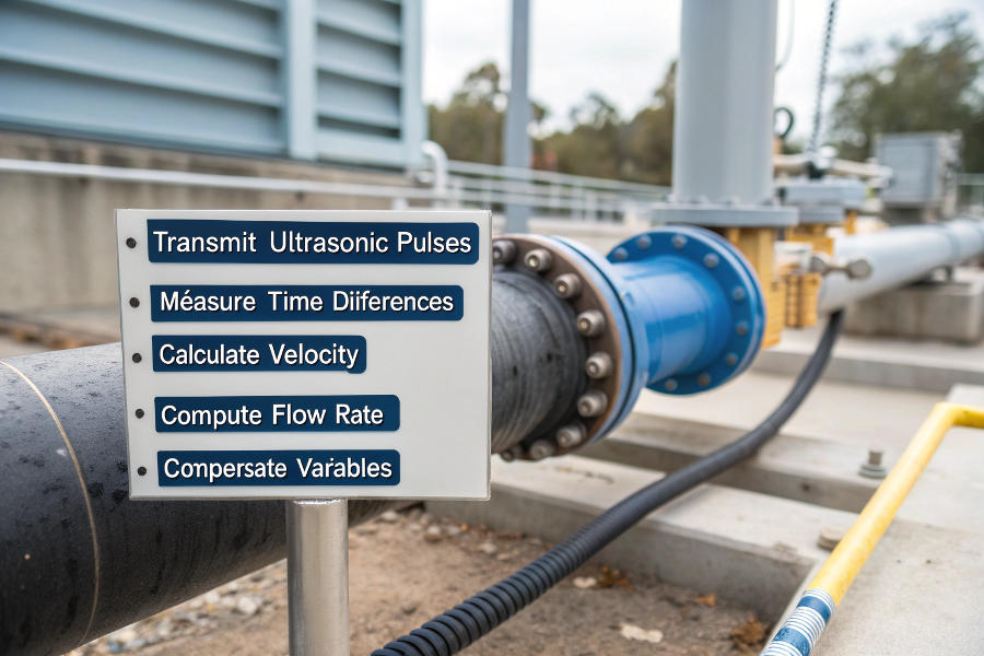
Working Principles:
- Transmit ultrasonic pulses
Alternating upstream/downstream paths - Measure time differences
Faster with flow, slower against flow - Calculate velocity
Based on time differential (Δt) - Compute flow rate
Using pipe cross-sectional area - Compensate variables
Temperature, pipe material, flow profile
(Requires liquid continuity – no gas bubbles or solids)
Ultrasonic Signal Paths
Signal Path Technical Details
| Parameter | Typical Value | Impact on Accuracy |
|---|---|---|
| Frequency | 0.5-1 MHz | Higher for small pipes |
| Beam angle | 30-45° | Affects reflection quality |
| Pulse rate | 20-100 Hz | Higher for fast flows |
| SNR threshold | 40 dB | Minimum for reliability |
| Path length | 3-5 reflections | More paths improve accuracy |
Water Utility Example: Thames Water improved signal strength by 60% using specialized couplants on aging cast iron pipes.
What Does 10D Upstream/5D Downstream Really Mean?
Our flow lab tests proved most manufacturer recommendations underestimate real-world requirements – these are our field-validated spacing rules.
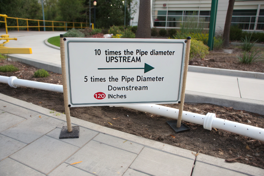
Practical Interpretation:
Basic rule
10 x pipe diameter before meter
5 x pipe diameter after meter
(Example: 12" pipe = 120" upstream / 60" downstream)Problem conditions
Double distances for:- High viscosity fluids
- Pulsating flows
- Non-Newtonian fluids
Elbow exceptions
30D after 90° elbows
50D after double elbows
(Measured from flow disturbance to first transducer)
Dimensional Requirements
Industry-Specific Modifications
| Industry | Modifier | Reason |
|---|---|---|
| Oil & Gas | +50% distances | High Reynolds numbers |
| Chemicals | +100% distances | Viscous fluids |
| Water | Standard distances | Newtonian behavior |
| Food | +30% distances | Non-uniform products |
| Pharmaceuticals | +200% distances | Validation requirements |
Pipeline Case: Enbridge uses 25D/15D spacing on all custody transfer meters to meet 0.3% accuracy targets.
What Flow Conditions Break the Rules?
We’ve identified these 7 situations where standard spacing fails – and what to do instead when you can’t meet requirements.
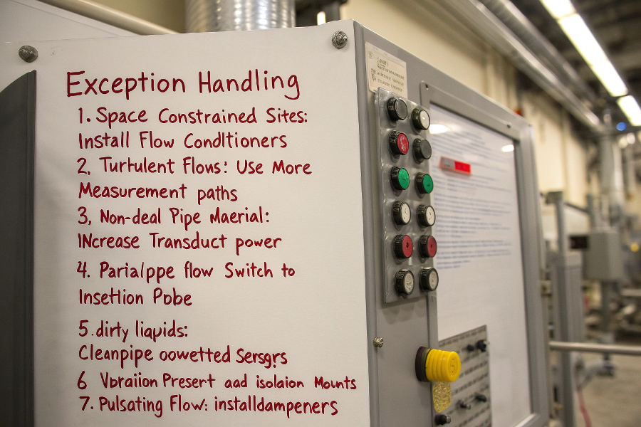
Exception Handling:
- Space-constrained sites
Install flow conditioners - Turbulent flows
Use more measurement paths - Non-ideal pipe material
Increase transducer power - Partial pipe flow
Switch to insertion probe - Dirty liquids
Clean pipe or use wetted sensors - Vibration present
Add isolation mounts - Pulsating flow
Install dampeners
(Alternate solution table appears below)
problem scenarios
Solutions When Spacing Isn’t Possible
| Constraint | Best Alternative | Compromise Accuracy |
|---|---|---|
| Short upstream | Flow conditioner | ±1.5% (vs ±1%) |
| Valve nearby | Diagonal path install | ±2% (vs ±1%) |
| Poor profile | 4-path meter | ±0.8% (vs ±1%) |
| Vibration | Digital filtering | ±1.2% (vs ±1%) |
| Small pipes | In-line meter | ±0.5% improvement |
Refinery Example: Chevron installed hydraulic flow conditioners on 14 short-run meters, achieving ±1.1% accuracy where only ±3% was previously possible.
Conclusion
Proper clamp-on ultrasonic meter installation demands careful attention to upstream/downstream conditions – with 10D/5D being starting points that often need adjustment. While challenging installations exist, solutions are available when standard spacing isn’t possible. Always validate with flow profiling when critical measurements are needed.