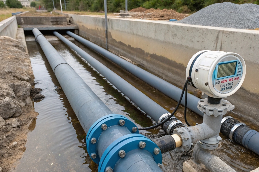
Installing a magnetic flow meter correctly ensures accurate, long-lasting performance.
Magnetic flow meters require specific piping conditions: 1) Full-pipe flow (except special non-full pipe models), 2) 10 pipe diameters straight run upstream (5D downstream), 3) Proper grounding, 4) Conductive fluids (>5 μS/cm), and 5) Correct pipe size matching the meter’s bore diameter.
Proper Magnetic Flow Meter Piping
From my experience supplying these meters globally, here’s what you need to know.
What Are the Requirements for Mag Meter Piping?
Piping setup is critical for signal stability.
The meter must be installed in sections with continuous pipe diameter1 (avoid reducers near electrodes), and pipe supports should prevent stress/strain on flanges. For slurry applications, vertical upward flow prevents settling, while gas pockets are avoided by ensuring venting capability at high points.
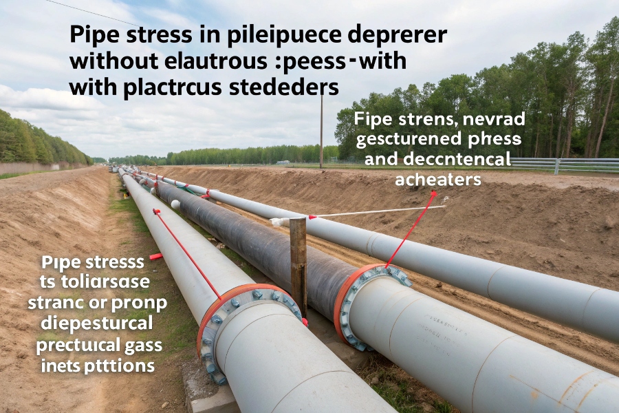
Pipe Stress and Alignment
Key considerations for optimal piping:
Piping Material & Alignment Guidelines
| Requirement | Specification | Common Mistakes | Solution |
|---|---|---|---|
| Pipe Material2 | Use same material as meter flanges | Mixed metals cause galvanic corrosion | Use insulating gaskets if necessary |
| Alignment3 | Axial misalignment <1mm | Poor fit-up induces stress | Use alignment clamps during install |
| Pipe Supports | Support nearby, not on meter | Inadequate supports cause vibration | Add rigid supports 1D away |
| Expansion Joints | Install at least 5D away | Joint turbulence affects flow | Maintain straight pipe requirement |
| Grounding | Dedicated grounding ring needed | Relying only on flange bolts | Install grounding electrode per manual |
What Are the Requirements for Electromagnetic Flow Meter Installation?
Installation position affects performance.
Best practices include: 1) Avoid top-dead-center installation where bubbles collect, 2) Horizontal mounting with electrodes at 3 & 9 o’clock for solids, or 4 & 8 o’clock for gases, 3) Ensure full submergence (or use non-full pipe models if needed), and 4) Always verify grounding resistance (<10Ω).
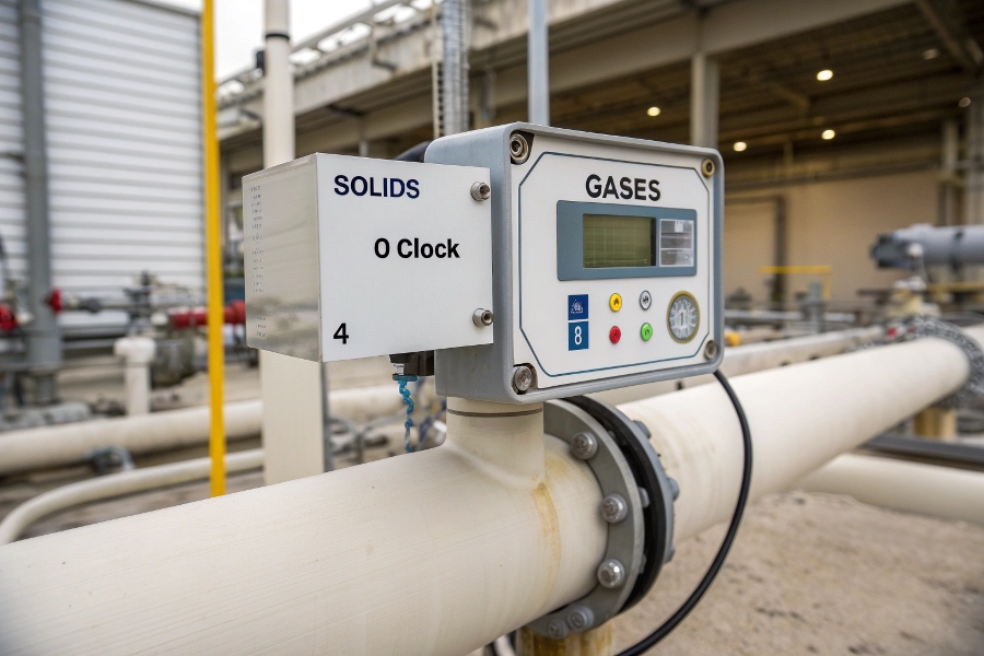
Electrode Positioning Guide
Proper orientation depends on fluid type:
Recommended Installation by Fluid Type
| Fluid Type | Best Orientation | Electrode Position4 | Why? |
|---|---|---|---|
| Clean Liquids | Any | 3 & 9 o’clock | Ensures electrode contact |
| Slurries/Solids | Vertical upward | 3 & 9 o’clock | Prevents particle settling |
| Gases/Bubbles | Horizontal or 45° | 4 & 8 o’clock | Lets bubbles rise away from electrodes |
| Non-Full Pipe | Special (weir/channel) | Side-mounted | Requires calibrated level-to-flow mapping |
What Is the Straight Pipe Requirement for a Flow Meter?
Undisturbed flow5 is essential.
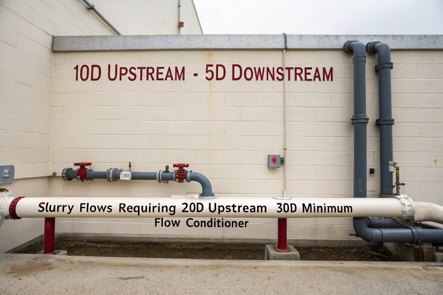
Standard straight pipe requirement is 10D upstream (5D downstream) to stabilize flow profile after disturbances like valves/pumps. Exceptions: slurry flows need 20D upstream, while installations after double elbows require 30D minimum or a flow conditioner.
Straight Run Requirements
More scenarios require adjustments:
Straight Pipe Rule Exceptions
| Obstruction Type | Minimum Upstream | Practical Workaround |
|---|---|---|
| Control Valve | 20D | Use flow conditioner if space limited |
| Pump Discharge | 30D | Install further away or dampen |
| T-Junction | 15D | Split flow symmetrically if possible |
| Butterfly Valve | 15D | Ensure full open position (>60° open) |
What Is the Rule of Thumb for Flow Meter Pipe?
Simplify basic guidelines.
General rules: 1) Always match pipe size (+/- 5% diameter variance), 2) Never install before flow disturbances, 3) Keep fluid velocity 1-3 m/s (0.3 m/s min for slurries), and 4) For non-full pipe applications, use venturi-style or open-channel mag meters with level compensation.
Ideal Flow Velocity Range
Quick reference for sizing and setup:
Flow Meter Piping Cheat Sheet
| Parameter | Ideal Range | Consequences of Deviation |
|---|---|---|
| Pipe Size Match | ±5% of meter diameter | Turbulence or signal loss |
| Velocity | 0.5–10 m/s (typical 1–3 m/s) | Too low: Poor signal / Too high: Erosion |
| Grounding | <10Ω resistance | Electrical noise issues |
| Non-Full Pipe | Requires special meter | Standard mag meters fail |
Non-full pipe electromagnetic flow meters are specialized designs (weir, flume, or channel types) that measure partially filled pipes by combining level sensors with velocity measurement. These require:
- Calibrated level-flow relationship
- Stable flow profile (no surging)
- Different K-factor calculations
Conclusion
Magnetic flow meters demand proper piping: full-pipe flow (unless using non-full models), correct straight runs, grounding, and positioning. Following these requirements ensures reliable, accurate flow measurement for years.
Understanding continuous pipe diameter is crucial for ensuring signal stability in mag meter installations. Explore this link for detailed insights. ↩
Understanding the right pipe material is crucial to prevent issues like galvanic corrosion and ensure system longevity. ↩
Proper alignment minimizes stress and enhances the efficiency of piping systems, leading to better performance and durability. ↩
Learning about optimal electrode positions can improve measurement accuracy and efficiency in fluid applications. ↩
Exploring the significance of undisturbed flow can enhance your knowledge of flow meter performance and installation best practices. ↩